Table of Contents
Static synchronous compensators (STATCOMs) are power electronic converters aiming at enhancing the overall power quality and system stability in power grids, by dynamically controlling the reactive power flow and reducing the voltage and current harmonics injected into the grid. [1]
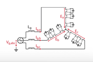
In medium voltage (MV) distribution systems, step-down transformers are commonly used in STATCOMs to reduce the voltage to levels supported by the power electronic switches [1]. Alternatively, cascaded multi-level topologies, such as the star-connected cascaded H-bridge, have been proposed to eliminate the costly and bulky transformer and thus connect the STATCOM directly to the MV grid [2].
This article presents a simple control implementation allowing the control of the reactive power flow at the point of common coupling (PCC) using the star-connected cascaded H-bridge STATCOM. The control strategy is then experimentally validated on a scaled-down prototype using the imperix MMC bundle programmed with the ACG SDK.
Control implementation of the STATCOM
The objective of the control presented in this article is the tracking of a desired reactive power setpoint at the grid terminal (PCC) when a test load is generating or consuming reactive power. Additionally, the capacitor voltages Vdc,i must be balanced to guarantee a safe and stable operation of the converter. The active reduction of the grid current harmonics is out of the scope of this example, and the test load is thus assumed to be a linear load.
The control of a cascaded H-bridge detailed in TN165 CHB control is used in this example, with the following adaptations:
- The grid currents Ig,abc are measured at the PCC and additional current sensors measure the STATCOM currents Is,abc.
- The active (d-axis) load current Iload,FF,d is reconstructed from Ig,d and Is,d and low-pass filtered to ignore possible harmonics at frequencies higher than the fundamental grid frequency.
- The output of the average DC-link voltage controller is the d-axis STATCOM current reference Is,ref,d instead of the d-axis grid current reference Ig,ref,d. Ig,ref,d is then obtained after feed-forwarding the d-axis load current Iload,FF,d.
- Since the converter currents are named Is instead of Ig, Is is used in place of Ig in the decoupling for the dq current control and in the voltage balancing.
The overall control block diagram is depicted in Figure 2. All blocks in black color are taken directly from the example TN165 CHB control.
Experimental validation of the STATCOM controller
Test setup
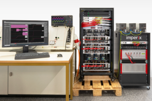
The control algorithm presented in the previous section is validated on a scaled-down prototype shown in Figure 3. The STATCOM is implemented using a slightly modified MMC bundle with 8 H-bridge modules (PEH2015) per phase and extended with 3 optical expansion boards to obtain 16 PWM signal pairs per phase. The grid is taken from the standard 230/400V 50Hz mains and the average DC-link voltage setpoint is chosen as 50V.
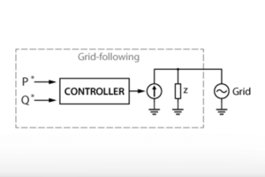
The test load is emulated using a programmable inverter (TPI8032), controlled as a grid-following inverter (see TN167 for an implementation example). This allows a freely selectable amount of reactive power to be generated or consumed.

Test results
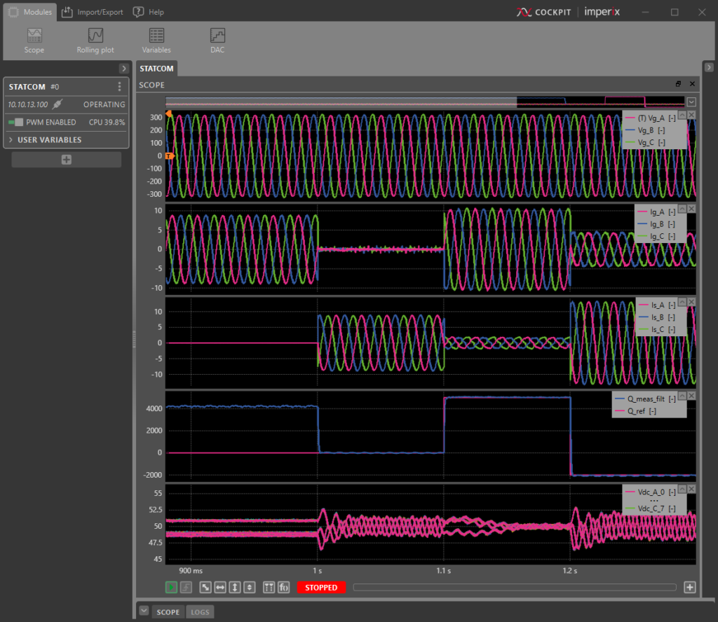
To validate the implemented control, the code generated by the ACG SDK is loaded onto the master B-Box RCP. The linear load emulated by the TPI using the control in TN167 is set to 4kVar (inductive behavior). In Cockpit, the following test sequence is initiated and a scope module monitors the relevant signals (Figure 4):
- t < 1 s: The STATCOM is inactive and the 4kVar generated by the load (TPI8032) flow into the grid.
- t = 1 s: The STATCOM is activated with a reference reactive power at the PCC of 0Var. This efficiently suppresses the grid currents Ig,a, Ig,b and Ig,c.
- t = 1.1 s: The reactive power reference at the PCC steps to 5kVar (inductive)
- t = 1.2 s: The reactive power reference at the PCC steps to -2kVar (capacitive).
During the whole test sequence, it can be seen that the 24 capacitor voltages Vdc,A0 to Vdc,C7 remain balanced despite unavoidable transient perturbations at the reactive power steps. The maximum transient imbalance does not exceed the amplitude of the voltage pulsation, which can be considered satisfactory.
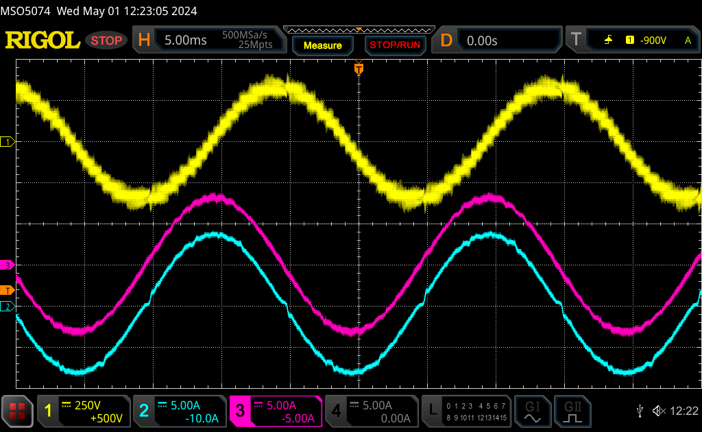
Additionally, the voltage generated by the STATCOM converter in phase A is measured using a differential voltage probe and an oscilloscope (CH1, yellow). It can be verified in Figure 5 that the voltage has a staircase shape with 2*N+1 = 17 levels. The screenshot in Figure 5 is taken at t = 1.05 s, when the STATCOM current (phase A, CH2, cyan) matches the purely reactive load current (phase A, CH3, magenta). This means that the grid current (difference between load current and STATCOM current) vanishes and the reactive power of the load is compensated by the STATCOM.
Downloads
Two sets of files are proposed, suitable for implementing the STATCOM control and simulating its behavior in MATLAB Simulink or Plexim PLECS environment.
Simulink model
PLECS model
Minimum requirements:
- Imperix ACG SDK 2024.1.1 or newer.
- For control code development and simulation in Simulink:
- MATLAB Simulink R2016a or newer
- For control code development and simulation in PLECS:
- Plexim PLECS 4.5 or newer.
To go further
Another possible application of the cascaded H-bridge control (TN165) used in this example with reactive power control is the MV-LV solid-state transformer (AN015).
In some applications, the reactive power flow at the PCC is used to stabilize the grid voltage. There, the reactive power setpoint is dynamically adjusted by a higher-level controller. This concept is for instance used in Proportional droop control (TN169), Virtual synchronous generator for droop control (TN170) and Virtual impedance for droop control (TN171).
Academic references
[1] Y. Liang, C. O. Nwankpa, “A New Type of STATCOM Based on Cascading Voltage-Source Inverters with Phase Shifted Unipolar SPWM,” in IEEE Transactions on Industry Applications, vol. 35, no. 5, September/October 1999.
[2] H. Akagi, S. Inoue, T. Yoshii, “Control and Performance of a Transformerless Cascade PWM STATCOM With Star Configuration,” in IEEE Transactions on Industry Applications, vol. 43, no. 4, July/August 2007.


