Table of Contents
This note gives the instructions to efficiently get started with the imperix ACG SDK on PLECS.
Related material
Suggested prerequisites
Suggested further readings
Prerequisites
Before starting, the following two steps must have been performed. They are described in Installation guide for ACG SDK (PN133)
- The imperix ACG SDK must be installed
- The imperix library must have been added to the target support packages path of PLECS coder. The imperix library is located in the Imperix_Controllers target support package contained within the ACG SDK installation. The default location is
C:\imperix\BB3_ACG_SDK\plecs.
First model
The best way to begin working with PLECS is to start from the template model. The default template model contains all basic configurations to start working right away.
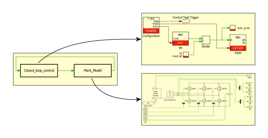
C:\imperix\BB3_ACG_SDK\plecsThe model is separated into two subsystems, the plant model and the closed-loop control as shown below:
- Plant_Model: contains the model of the system to be controlled. This is typically the model of the power system itself (e.g. converter, sources, grid, machine, sensors,…).
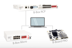
- Closed_loop_control: contains the control implementation that can be simulated or used to generate the control code for the imperix controller (B-Box RCP, B-Box Micro, or B-Board PRO).
Plant model subsystem
In order to run the control algorithm in simulation, PLECS needs a model of the real converter hardware (system to be controlled). This model should be located inside the Plant_Model subsystem of the root view of your PLECS model.
The plant model is usually only considered during offline simulation. Indeed, code for an imperix controller cannot be generated from the plant model. A PLECS RT Box target can be used to perform HIL emulation of the plant model.
Closed-loop control subsystem
Imperix control library
The control implementation can be done using the blocks provided in the Imperix Control Library and most PLECS blocks from the PLECS standard libraries.
The Imperix Control library can be found in the library browser (Window > Library Browser or by pressing [CTRL+L] and browsing to Imperix Control).
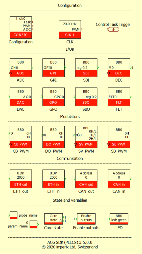
The Imperix Control library shown on the right essentially implements hardware-related mechanisms that are associated with analog and digital I/Os. The library also contains blocks for real-time monitoring and to control the state of an imperix controller.
Basic control example
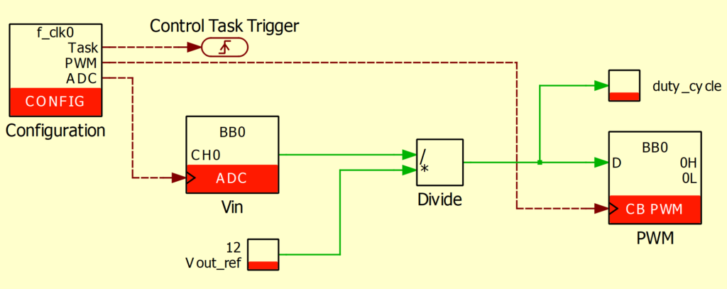
For the sake of example, a basic control algorithm of a buck converter is shown below. It sets the output voltage to 12V, regardless of the measured input voltage.
Note that the ADC input Vin and the CB_PWM PWM output are automatically added to the Closed_Loop_Control subsystem inputs/outputs. They should be connected to the Plant_Model subsystem for simulation purposes, as shown in the screenshot below.
This basic control scheme contains:
- A CONFIG block to define the main interrupt frequency and ADC sampling phase shift and postscaler
- A Control Task Trigger block used to set the atomic subsystem’s discretization step size
- An ADC block to retrieve the simulated DC bus voltage in simulation, and the analog input on channel 0 of the imperix controller in code generation
- A Tunable Parameter block to define a variable
Vout_refthat is accessible and modifiable in real-time from the Cockpit software - A Probe block to define a variable
duty_cyclethat can be logged in real-time from the Cockpit software - A Carrier-based PWM (CB_PWM) modulator to generate PWM signals with a duty-cycle D. The PWM signals are wired to the plant model in simulation and directly output on the PWM outputs of the imperix controller in code generation
Simulation
The Plant_Model subsystem is simulated using the solver parameters specified in Simulation > Simulation Parameters… > Solver.
For the Closed_Loop_Control subsystem, the values going through the ADC blocks are sampled with the sampling clock provided by the CONFIG block.
The whole control algorithm is executed at the main interrupt rate, defined by the variable f_clk0. This variable can be configured in Simulation > Simulation Parameters… > Initialization.
See the section “Main interrupt frequency and discretization step size” below to learn how f_clk0 variable is tied to the main interrupt frequency and the discretization step size.
Code generation for an imperix controller target
To generate code for an imperix controller from the Closed_Loop_Control substem, press on [CTRL+Alt+B] or click on Coder > Coder Options to open the Coder Options window.
If you started from the default template model everything will be configured as showed below.
To launch the code generation process simply press the build button. It will generate the CPU code, and Cockpit will be automatically launched. Cockpit will then load the code onto the target (B-Box RCP, B-Box Micro, or B-Board PRO). More information on Cockpit is available on Programming and operating imperix controllers (PN138).
Detailed configuration of an imperix model
This chapter contains a step by step explanation of how the default template model or example models are created and configured to properly work with an imperix controller.
Subsystem creation
To create a Closed-loop control subsystem or a Plant model subsystem starting from a blank model, simply follow the next few steps:
1. Press [CTRL+L] to display the Library Browser. Type subsystem in the search bar to quickly find the component
2. Drag and drop the subsystem block to your model
3. Rename the subsystem to Closed_loop_control or Plant_Model by double-clicking on the subsystem block name
4. Open the subsystem and remove the preexistent Signal Inport and Outport. Replace it with the desired blocks.
Main interrupt frequency and discretization step size
A key aspect of simulation and code generation is the discretization step size. It specifies the base sample time of the generated code and is used to discretize the continuous control algorithms developed by the user. If the control is already discretized, it sets the sample time of the discretized blocks. The blocks from the Imperix Control library, on the other hand, must be discretized at main interrupt frequency.
To ensure that the discretization step size matches the main interrupt frequency, proceed as follows:
- Add a CONFIG block and set the Clock frequency parameter to
f_clk0. This will set the main interrupt frequency. - Add the Control Task Trigger block and set Nominal base sample time to
1/f_clk0. It will set the discretization step size. - Define the variable
f_clk0and set it to the desired sampling frequency (in this case 20 kHz). It can be achieved by clicking on Simulation > Simulation parameters > Initialization and add the following line in the Model initialization commands box:f_clk0 = 20e3; - Make the Closed-loop control subsystem atomic to ensure the same sample time throughout the control. Right-click on the Closed_loop_control subsystem, click on Execution Settings and tick the Treat as atomic unit checkbox.
Setting up the model for code generation
Enabling code generation
The first step is to enable code generation for the Closed_loop_control subsystem. To achieve it, simply right-click on the Closed_loop_control subsystem, click on Subsystem > Execution Settings…, and tick the Enable code generation checkbox. If the discretization step size was previously set up (as explained in the section above), the Discretization step size parameter should already be configured to 1/f_clk0.
Target Configuration
The last step is to set the Target used for code generation.
It can be done by clicking on Coder > Coder Options. Be sure to select the Closed_loop_control system.
In the General tab, make a quick check to ensure that the Discretization step size is set to the desired value of 1/f_clk0.
Everything is now set and ready to generate C++ code.


