TPI SB-PWM – Helper block
The TPI SB-PWM helper block is a wrapper that simplifies the use of the SB-PWM block with the all-in-one programmable inverter (TPI8032 22kW). The TPI…
The TPI SB-PWM helper block is a wrapper that simplifies the use of the SB-PWM block with the all-in-one programmable inverter (TPI8032 22kW). The TPI…
The angle generator block contains a counter that continuously outputs the current value of the angle, wrapped between the chosen lower and upper limits, with…
The PEB block is a simulation model included in the Imperix Power library. It models the imperix half-bridge module PEB-800-40, PEB8038, PEB8024, and PEB4050 in…
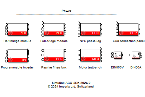
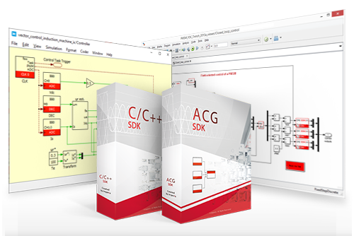
The imperix Power library is a blockset contained within the imperix ACG SDK, which contains accurate models of imperix power products. This article summarizes the…
This page introduces the implementation of a solid-state transformer with cascaded H-bridge, dual active bridge, and grid-forming inverter.
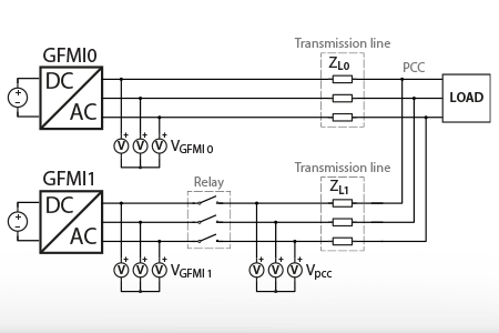
This note introduces the parallel operation of Grid-Forming Inverters (GFMIs) and provides an implementation example on TPI 8032 programmable inverter with the ACG SDK. An…
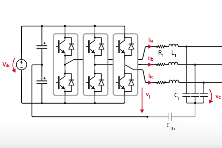
This article introduces an example of Finite Control Set Model Predictive Control (FCS-MPC) for an LCL-filtered voltage-controlled inverter. The proposed control implementation is derived from…
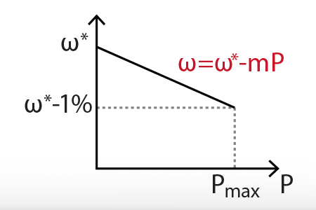
Droop control algorithms are utilized to wirelessly regulate the power-sharing among grid-forming inverters (GFMIs) in microgrids, regardless of whether they operate in standalone or grid-connected…
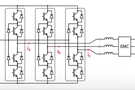
Closed-loop current control for a grid-tied Neutral Point Clamped (NPC) inverter. The considered setup is a three-phase three-wire NPC inverter supplied by a DC source and connected to the grid.
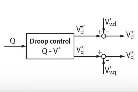
This note introduces the virtual impedance method for power decoupling in resistive lines. An implementation example is provided to validate the virtual impedance method with…
End of content
End of content