Table of Contents
This example implements the control for a three-phase PV inverter. Such a system can be typically found in small industrial photovoltaic facilities, which are directly connected to the low voltage power grid.
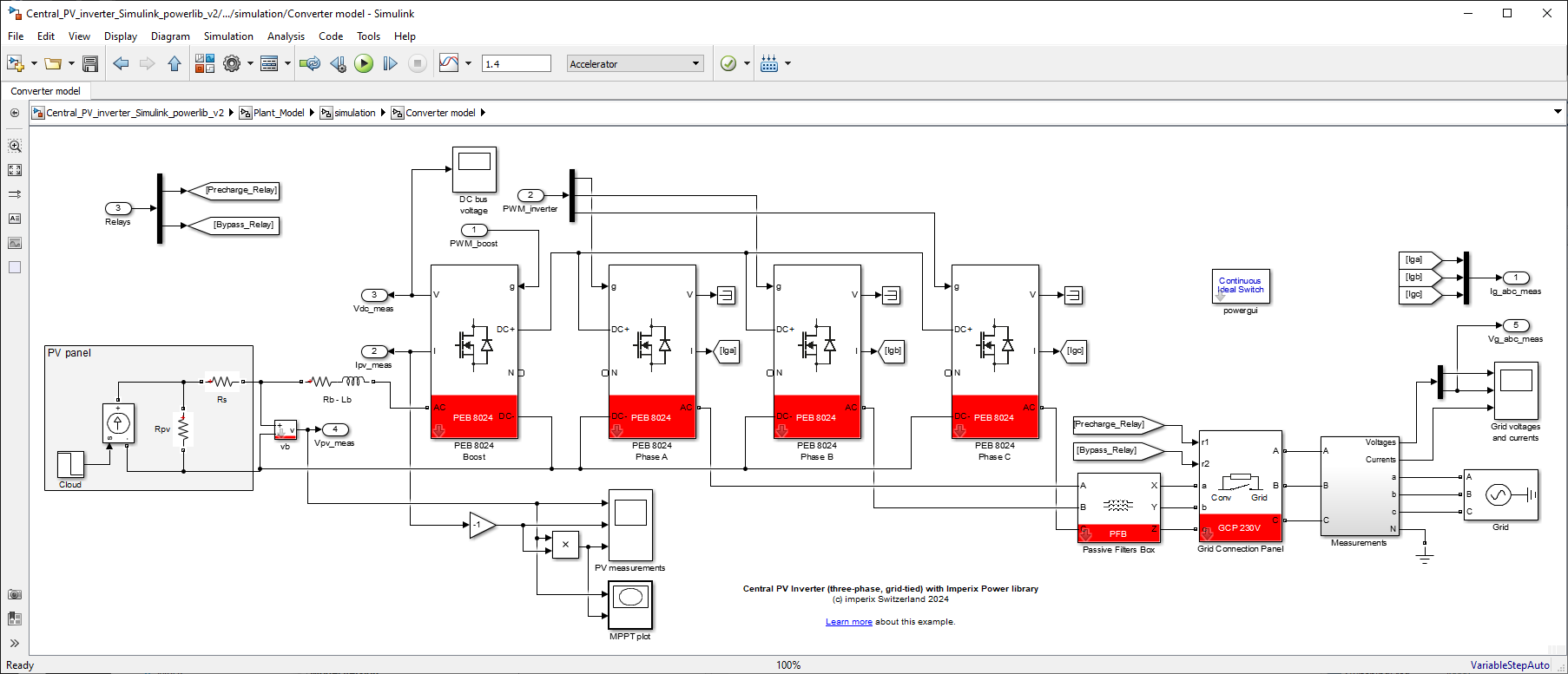
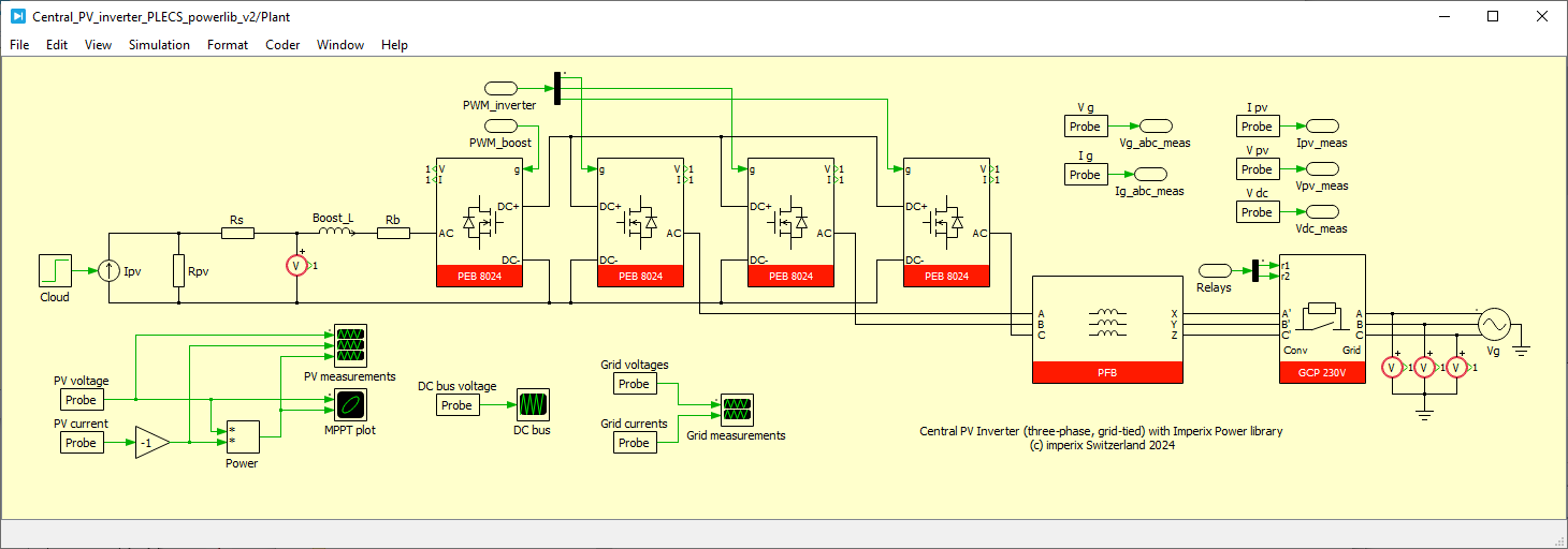
The presented system implements a dual-stage conversion structure, using a boost DC/DC stage in order to raise the voltage of the PV panel to an intermediate DC bus, as well as a conventional DC/AC Three-phase Voltage Source Inverter (VSI) for the connection to the grid.
As such, the system is similar to that of AN003, except that the inverter is a three-phase variant.
Downloads
Two sets of files are proposed, suitable for implementing the control and simulating its behavior in MATLAB Simulink or Plexim PLECS environment.
Imperix Power library requires ACG SDK 2024.2 or a later version. To update the ACG SDK, please go to imperix.com/downloads/.
The file below contains the PLECS model with a Hardware-In-the-Loop (HIL) configuration that can be used with the B-Box RCP together with a Plexim RT-Box.
Minimum requirements:
- Imperix ACG SDK 3.6 or newer.
- For control code development and simulation in Simulink:
- MATLAB Simulink R2016a or newer.
- Simscape Power Systems
- For control code development and simulation in PLECS:
- Plexim PLECS 4.5 or newer. The HIL version also requires the PLECS_RT_Box target support package.
Finally, the C code corresponding to the same control implementation is also available below.
Implementation of a GUI
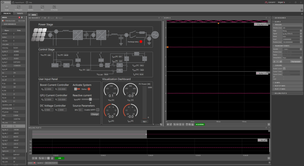
Since the release of ACG SDK 2025.1 and CPP SDK 2025.1, Cockpit introduced the ability to build a GUI using the GUI Builder module. A GUI can be exported as a *.ixgui file, and later reimported on a different in different projects.
A pre-implemented GUI for AN006 is shown in the figure on the left and can be downloaded using the link below:
Control implementation of the three-phase PV inverter
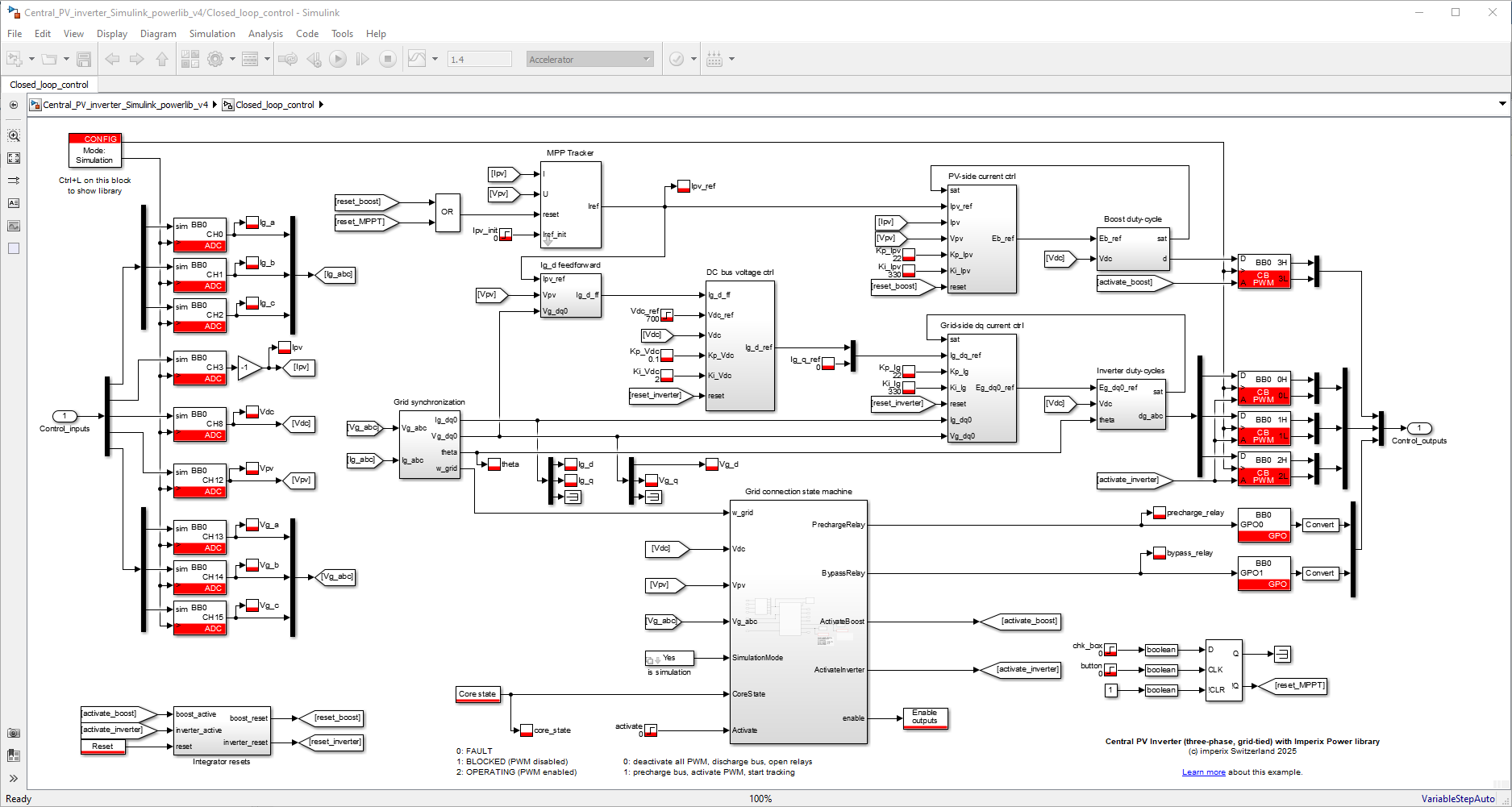
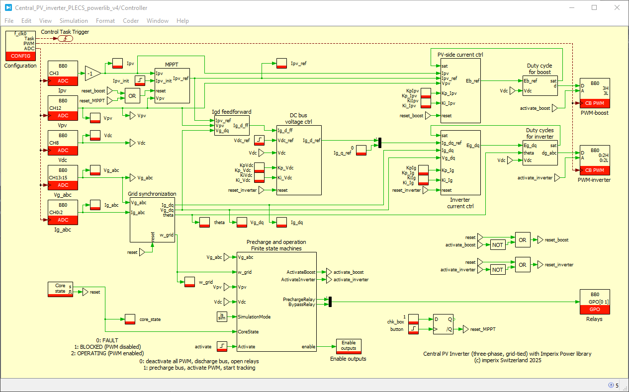
The overall control implementation corresponds to the following design choices:
Grid-side control
- Synchronization with the grid is made using a conventional quadrature PLL.
- The grid current control is achieved using a conventional vector current control in the rotating reference frame (dq). The corresponding technique is detailed in TN106.
- The DC bus voltage is controlled from the grid side, using a cascade on top of the current control. A conventional PI controller is used. More details on the approach are available in TN108.
PV-side control
- On the PV side, a basic current control of a boost converter (TN101) is implemented (see details in TN105). The current reference is set from a Maximum Point Point Tracking algorithm, as detailed in TN117.
Precharge and operation state machines
- The DC bus precharge and the operation of the converter stages are managed by a finite-state machine.
- The user action variable is “activate”. When set to 1, the precharge of the DC bus from the grid starts. The Precharge state machine closes the precharge relay and waits until the DC bus reaches its minimum value. Then, it closes the bypass relay and outputs “Ready to operate”.
- Once the Precharge state machine indicates “Ready to operate”, the Operation state machine activates the converters and closes the PV-side relay. This starts the MPPT algorithm (boost current control) and the cascaded DC bus and grid current regulations.
Simulation results of the three-phase PV inverter
MATLAB Simulink
The example models available for download at the top of this page have the following simulation scenario, which is illustrated by the simulation results below:
- At t=0, the DC bus is already precharged at 500V and the PWMs are not yet activated.
- At t=0.1s, the “activate” variable is set to 1. The PWMs are immediately activated (FSM is bypassed in simulation), the DC bus voltage is regulated at 750V, and the MPPT algorithm converges gradually to the MPP (corresponding to a PV current reference around 18A).
After the MPPT algorithm has converged (after t=0.22s), the Perturb and Observe algorithm gives a PV current reference that oscillates around the MPP current. - At t=0.5s, the DC voltage reference is reduced to 700V.
- At t=0.8s, the solar irradiance is reduced (simulation of passing clouds). The MPPT algorithm gradually decreases the PV current reference and reaches the new MPP at around t=1s (corresponding to a PV current reference around 15A).

HIL simulation results
HIL simulation allows further tests on the Precharge and Operation state machines. The following results are obtained when executing the control code on a B-Box RCP, and the plant model on an RT-Box.
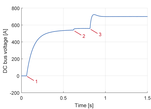
The figure below shows the evolution of the DC bus voltage during the precharge when starting from an empty bus. The point (1) corresponds to the user changing the variable “activate” from 0 to 1. This has the effect of closing the precharge relay and the DC bus is charged from the grid, through the precharge resistors and the converter diodes. Point (2) is where the voltage reaches the minimum bus voltage, which closes the bypass relay. 200 ms later, at (3), the boost and inverter stages are activated and the DC bus is regulated at 700V.
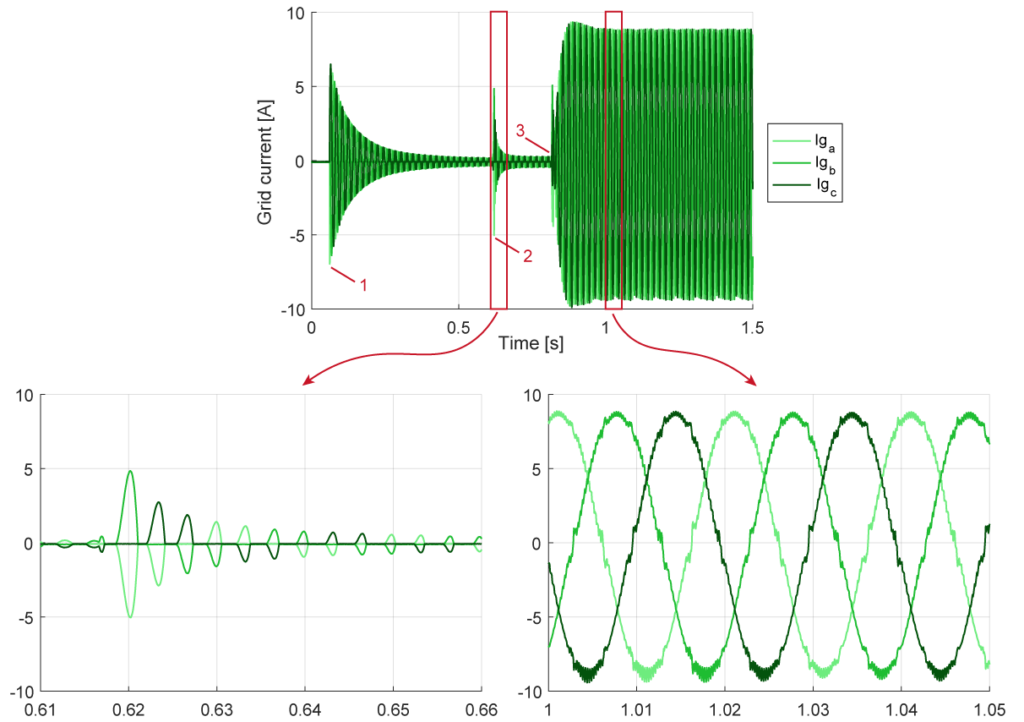
During that procedure, the grid currents are shown below. At steps (1) and (2), they are rectified currents flowing through the converter diodes, and after (3), during normal operation, they are sinusoidal currents with d- and q-axis components controlled by the algorithm.
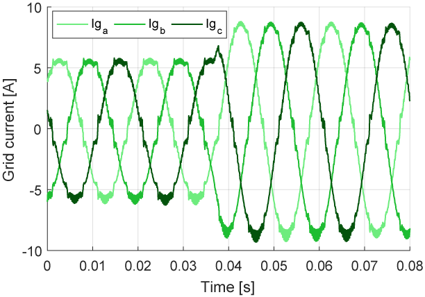
During normal operation, the grid current amplitude will depend on the power produced by the PV panel. The figure below shows the effect of a step in the solar irradiance on the grid current amplitude:
Quick-start guide for operating the three-phase PV inverter
The objective of this section is to provide the main steps to operate the three-phase PV inverter. For a detailed guide on how to build and test one from the power electronics test bench, please refer to PN171.
Required hardware
Experimentation on this Application Note can be made using standard imperix equipment:
- 1x “Type C” rack with 4x PEB8038 (or PEB8024) modules
- 1x passive filters rack or:
- 3x 2.2mH inductor (Lg)
- 1x 2.2 mH inductor (Lb)
- 4x DIN800V voltage sensors
In addition, the following equipment is needed:
- 1x PV panel or PV panel emulator
- 1x AC disconnector, or better controllable relay as well as a circuit breaker.
- 1x isolation transformer (optional, refer to the datasheet of the passive filters rack for the connection to grid without a transformer)
- (1x pre-charge circuit – optional, not shown)
I/O signals
Controller inputs (sensors)
| Analog input channel | Measured quantity | Sensor |
|---|---|---|
| AI0-2 | Grid currents (Ig_abc) | embedded on PEB8038 (or PEB8024) |
| AI3 | PV current (Ipv) | embedded on PEB8038 (or PEB8024) |
| AI8 | DC bus voltage (Vdc) | embedded on PEB8038 (or PEB8024) |
| AI12 | PV voltage (Vpv) | DIN800V |
| AI13-15 | Grid voltages (Vg_abc) | DIN800V |
Controller outputs (PWM signals)
| PWM channel (lanes) | PWM signals |
|---|---|
| CH0 (LN0-1) | Grid-tied inverter, phase a |
| CH1 (LN2-3) | Grid-tied inverter, phase b |
| CH2 (LN4-5) | Grid-tied inverter, phase c |
| CH3 (LN6-7) | Boost converter (high-side signal for reverse conduction in the MOSFET) |
Start-up procedure
The following steps can be used as a brief reminder of a reasonable start-up procedure:
1) Before addressing this application, run a simpler control code in order to validate that:
Protections are correctly configured and do trigger at the appropriate value.
2) Pre-charge the DC bus to a sufficient voltage to avoid any risk of uncontrolled diode conduction. In three-phase applications, the minimum DC bus voltage is defined by the peak line-to-line voltage of the grid.
3) Physically connect the converter to the grid, either using a controllable relay or using manual wiring.
4) In Cockpit, enable PWM operation. Related getting-started instructions are available in Programming and operating imperix controllers (PN138).
Operating the GUI
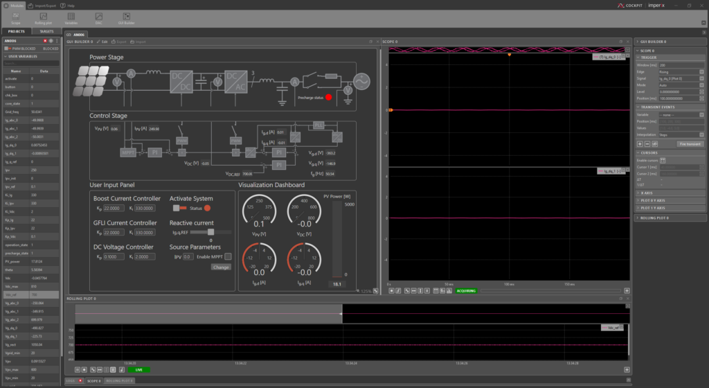
While not mandatory, creating a GUI in Cockpit is an effective tool to facilitate interactions with the controller. The GUI example for the three-phase PV inverter has the following features to control the system:
- A toggle to activate the automatic precharge and control of the converter
- Entry fields to change the values of the PI controller gains
- A slider to control the reactive current injected into the grid
- As well as a checkbox to enable or disable the MPPT tracker
In terms of data visualization, the GUI example for the three-phase PV inverter has the following features:
- A dynamic visual of the current status of the system, including the position of the grid connection relays
- Gauges to visualize system voltages and currents
- A thermometer module to show the power extracted from the PV panel
As the GUI builder module permits customization by the user, users can use the example above as a starting point and modify it to their needs.


