Table of Contents
This article provides getting-started instructions for first-time users of the imperix ACG SDK. It focuses on the typical workflow for simulation and automated code generation with imperix controllers. It notably addresses:
- Product presentation: What the ACG SDK is, and what pieces of software it contains.
- Resources: How the imperix blocksets can be used and how the files are typically organized.
- Simulation: How to effectively run accurate offline simulations.
The article focuses on developing code for the controllers’ CPU. Information on implementing programmable logic on the devices’ FPGAs is provided in PN169. Similarly, users interested in writing C/C++ code manually (rather than using code generation) should refer to a separate article on the CPP SDK.
Recommended articles related to the ACG workflow are shown below. A series of video tutorials is also available with similar content.
| Step | Documentation | Videos | |
|---|---|---|---|
| 1. Software installation | Installation guide for the ACG SDK PN133 | N/A | |
| 2. Getting started | Getting started with the ACG SDK PN134 | Create the model Video 1 | |
| 3. Running simulations | Simulation essentials with Simulink PN135 | Simulation essentials with PLECS PN137 | Simulate it Video 2 |
| 4. Device programming | Programming and operating imperix controllers PN138 | Generate code Video 3 | |
| 5. Monitoring | Cockpit user guide PN300 | ||
Pre-requisites
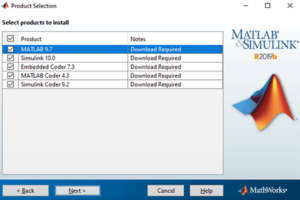
- Working with MATLAB requires Simulink, MATLAB Coder, Simulink Coder, and Embedded Coder. Similarly, working with PLECS requires PLECS Coder. Instructions for installing these software tools are given in PN133.
- The ACG SDK can be installed freely, but a license is required to execute the runtime code on a controller. More information on licensing is given in PN160.
Product description
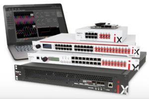
The ACG SDK is a Software Development Kit (SDK) that complements MATLAB/Simulink or PLEXIM/PLECS. It enables engineers to program imperix controllers directly from these software tools. It includes:
- A Control library for Simulink and PLECS. This blockset contains precise simulation models of the controller peripherals (used in offline simulation mode) as well as configuration methods for the same peripherals (used in code generation mode).

- A Power library for Simulink and PLECS. This blockset is used only in offline simulation mode and contains simulation models of Imperix's power products (e.g., power modules, filters, motors). In Simulink, both Simscape Electrical and Specialized Power Systems are supported.

- All additional necessary software and tools, such as compilers and scripts.
- The embedded operating system for the controllers.
- The standard FPGA firmware.
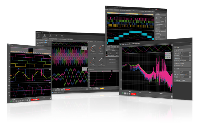
- The Cockpit monitoring software. It enables real-time interaction and monitoring of the physical converter by providing access to the model variables and all the signals measured by the programmable controllers.
Typical workflow
Regardless of the programming environment, the development typically proceeds as follows:
- Developing a Simulink or PLECS model that supports both offline simulation and code generation, according to the following typical steps:
- Opening an existing example from the knowledge base, creating an empty Simulink/PLECS file, or starting from an empty imperix template.
- Implementing the control algorithms using standard Simulink/PLECS blocks as well as dedicated hardware blocks from the imperix Control library.
- Modeling and simulating the complete system using the imperix Power library to support the pre-validation of the control algorithms during offline simulations.
- Tuning of the implemented control using offline simulations.
- Generating and compiling code directly from within Simulink or PLECS.
- Using Cockpit, corresponding to the following steps:
- Connecting to the target hardware - i.e. the controller - and flashing the generated runtime code.
- Launching the code and executing all further interactions with the hardware, such as real-time debugging, parameter tuning, monitoring and logging.
Developing a Simulink/PLECS model
During this first phase, the control software (i.e., the set of control algorithms) is developed, and its behavior is tested in an offline simulation before deployment on the controller. There are essentially five steps:
1. Opening an existing/new model
Essentially, three options are available:
- Most users prefer to start with an example from the imperix knowledge base, which offers the benefit of being pre-configured and generally reasonably close to the final application. Once downloaded, the example file can be copied or renamed (as long as the rules for MATLAB file naming are observed).
- Starting from an empty file is also possible. However, with Simulink, using a basic template is recommended because it provides a clean separation between the controller and plant (see below). The imperix base template is always located in
[installation_path]\user_template\imperix_template.slx - Existing models can be adapted to support both simulation and code generation. In PLECS, this is trivial. However, in Simulink, a good understanding of the software's configuration is necessary. Further information is given in PN143.
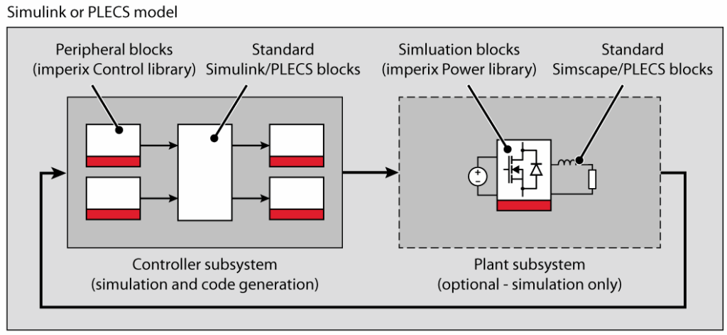
The vast majority of examples available on the knowledge base are organized with two main subsystems:
- The controller subsystem includes the control implementation, which can be simulated or used to generate real-time code. This subsystem also contains the CONFIG block, which is responsible for model configuration and certain global hardware parameters.
- The plant subsystem contains the model of the system to be controlled, whereas the controller side contains the controller. This is typically the model of the power system itself (e.g. converter, sources, grid, machine, sensors,…).
A typical arrangement of the overall model is shown below:
2. Implementing the control algorithms
With Simulink or PLECS, application-level control algorithms can be easily developed, similar to any other simulation model, thanks to numerous pre-existing blocks. Indeed, both Simulink and PLECS are specifically designed to enable automated code generation from the vast majority of their blocks. In practice, only the few blocks that lead to non-deterministic execution in real time are not supported (this is notably the case for some optimization algorithms, which feature a non-predictable convergence time).
In addition to the standard blocksets, the ACG SDK provides two libraries specifically for imperix products:
- The Control library contains target peripheral blocks, i.e., functions and resources specific to imperix control equipment, such as ADC, PWM, GPI/GPO, etc., as well as communication options. These blocks are typically used on the controller side of a Simulink/PLECS model.
- The Power library contains simulation models for individual imperix power products - such as the PEB modules - or system-level components like the motor test bench or the programmable inverter. These blocks are typically used on the plant side of a Simulink/PLECS model. Specific getting-started instructions are provided in Getting Started with the Power Library.
In PLECS, pressing Ctrl+L can be done at any time.
3. Modeling and simulating the system
With the imperix ACG SDK, a unique Simulink or PLECS model (i.e., a single file) can be used for both simulation (offline, on a computer) and code generation (i.e., the production of a binary executable for real-time use on a controller). There are hence two possible model execution purposes:
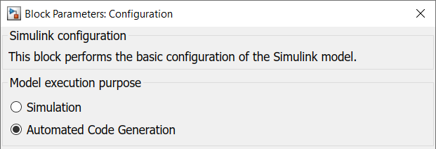
- In Simulation mode, the complete Simulink/PLECS model is simulated, including both the Controller and the Plant subsystems. The model uses the configured solver parameters (see below).
- In Automated Code Generation mode, C++ code is automatically generated by the Simulink/PLECS Coder engine. All signals coming to and from the Plant subsystem are ignored and replaced by the analog and digital inputs/outputs of the real hardware.
As such:
- The Controller subsystem is useful for both offline simulation and code generation. To support this, each block of the Control library contains two subsystems:
- One for simulation (offline) that holds an accurate model to simulate the controller hardware itself (e.g., execution delays, driver latencies).
- One for code generation (runtime) that translates data flows and parameters from the graphical model directly into calls to the underlying C/C++ hardware driver routines.
- The Plant subsystem is only considered during offline simulation. As such, blocks from the Power library contain only a simulation model and do not generate any code during code generation.
In Simulink, the model execution purpose can be selected in the CONFIG block (see below). In PLECS, both simulation (Ctrl+T) and code generation (Ctrl+Alt+B) can be launched without first making such a selection.
Control discretization and sampling
To accurately represent real-world operation, where the control implementation is executed within a CPU interrupt routine, that portion of the model must be simulated with a discrete time step corresponding to that interrupt execution rate. By contrast, the rest of the model (the content of the Plant subsystem) is best represented by continuous-time signals to accurately simulate physical electrical dynamics.
The peripheral blocks from the Control library (such as ADC and PWM) serve as the essential interface between these two domains. Their integrated simulation models ensure that sampling instants, carrier phase shifts, execution times, and various hardware delays are accurately modeled.
To ensure accurate modeling and valid offline simulation, these mechanisms must be well understood. Because their implementations vary, users should consult the environment-specific documentation to ensure accurate modeling in either Simulink or PLECS. Further details are provided in the following dedicated pages:
Users interested in learning more about how imperix controllers operate can refer to PN261. More details on their firmware architecture and the FPGA-based resources are also provided in PN253.
4. Tuning the control algorithms
The simulation models provide realistic results because the relevant dynamics are accurately represented in both the controller and the plant. On the controller side, effects such as computation time and driver delays are explicitly modeled in the Control library blocks, whereas the plant is accurately modeled using the Power library. This level of fidelity allows the control implementation to be validated in offline simulation and enables controller tuning even before generating the runtime code.
It is therefore highly recommended to first test and validate the control implementation in simulation, as this significantly reduces the time required for laboratory validation.
For readers seeking a deeper understanding, additional information on the interrupt-based control execution is given in PN261. The common sampling configurations are also presented in PN259.
5. Generating real-time code
Once validated in an offline simulation, the control code can be automatically generated for deployment on an imperix controller. This procedure uses automated code-generation tools from Simulink or PLECS that leverage the target-specific drivers embedded in each peripheral block of the Control library.
The build procedure varies slightly between the Simulink and PLECS environments. The exact procedures are detailed in PN138, but are as simple as:
- On Simulink, set the Model execution purpose to "Automated Code Generation" in the CONFIG block, select the right controller generation in the "Code gen." tab, and build the model (Ctrl+B shortcut).
- On PLECS, in the Coder > Coder option window, select the right target generation from the target list, and click the "Build" button.
This process translates the graphical model into C++ code and compiles it with target-specific drivers for peripherals like ADCs and PWM modules. It is mandatory to specify the controller generation (Gen 3 vs. Gen 4) during this stage, as the compilation must account for hardware-specific instructions and unique memory architecture.
At the end of a successful build, an executable (.elf) is generated for flashing onto the controller, as described in the subsequent section.
Programming the hardware controller
After the code is generated from the Simulink or PLECS model, the next steps are:
1. Flashing the code
As introduced in PN138, to flash the code onto an imperix hardware controller, users must first establish a connection between the host PC and the target(s) using an Ethernet cable. The connection can be direct (point-to-point) or through an Ethernet local network.
When Cockpit is launched, it automatically creates a new project with the executable path pre-filled. Deployment is achieved by clicking "Link target" and selecting the desired target from the list of detected targets. The code is then automatically downloaded and launched on the selected target. More details on this procedure are provided in PN138.
2. Interacting with the target
Once the code is running, interaction is primarily managed through Cockpit, where the operator must explicitly enable PWM outputs to generate gating signals, even though the control algorithm runs continuously upon launch. Users can monitor and modify defined variables in real time using modules such as the Scope, Rolling Plot, or Variables module, and tune parameters without stopping execution. Comprehensive instructions on using these tools can be found in the Cockpit user guide. Furthermore, most actions performed in Cockpit can be scripted and automated via the Python API.
Further readings
After a first code has been generated and tested, it is highly recommended to read the following pages, which provide tips and tricks specific to the employed software environment:
- Simulation essentials with Simulink guides the reader through offline simulation using Simulink.
- Simulation essentials with PLECS guides the reader through offline simulation using PLECS.
 By Julien Orsinger • March 25, 2021 • PN133
 By Nicolas Cherix • November 24, 2025 • PN160