Table of Contents
Imperix’s standard workflow programs the CPU of programmable controllers from Simulink, PLECS, or the Imperix IDE using the ACG SDK or CPP SDK. This proves to be simple and rapid to implement, while offering very attractive performance. On the other hand, some advanced applications may require more flexibility, which calls for programming the controllers’ FPGA as well. On imperix products, FPGA programming is possible at no additional cost.
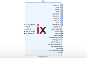
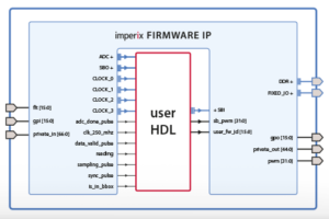
On imperix controllers, programming the FPGA requires instantiating the imperix firmware IP (which contains the imperix proprietary FPGA logic) using the AMD/Xilinx Vivado Design Suite. The surrounding programmable logic, known as the FPGA sandbox, can then be edited to suit the application.
This article presents how to get started with FPGA programming. It notably covers:
- The configuration of the AMD Vivado environment
- The creation of the Vivado FPGA sandbox template.
- The generation and deployment of a bitstream to the target controller, via a “Hello World” example.
Getting started with FPGA programming
Installing Vivado
The first step to install Vivado, which is available for free as the ML Standard edition. The recommended version is Vivado 2023.2, matching the internal development environment at imperix, although newer releases are also supported. It can be acquired through the AMD Unified Installer available on the AMD download page. During installation, the correct device support must be selected depending on the target:
- Zynq-7000 support for Gen 3 devices (B-Box 3, B-Box Micro, B-Board PRO, TPI8032)
- Zynq UltraScale+ MPSoC support for Gen 4 devices (B-Box 4)
The detailed installation procedure is described in PN168. Unless explicitly stated otherwise, the FPGA development documentation and procedures apply to both controller generations.
Creating the Vivado FPGA sandbox template
The FPGA sandbox template source files are available on the FPGA sandbox download page. These files are provided as a *.zip archive. They include:
- The imperix firmware IP, documented in PN116.
- The create_project.bat script, which automates the creation of the ready-to-use Vivado sandbox template project.
- VHDL helper modules to make FPGA development easier (AXI4-stream interfaces, carrier-based modulator, etc.)
The project creation procedure for the FPGA sandbox template is the following:
- Download the source FPGA_Sandbox_template_*.zip archive.
- Unzip it and save the content somewhere on the PC.
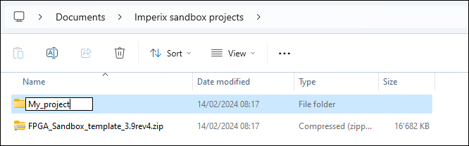
- Rename the folder to something more explicit.
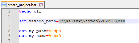
- Open scripts/create_project.bat using a text editor.
- Set the
vivado_pathvariable to match the Vivado version installed on the PC.
- Double-click on scripts/create_project.bat.
If a Windows Defender SmartScreen warning appears, click More info and select Run anyway to proceed. - Enter a project name and click Enter.
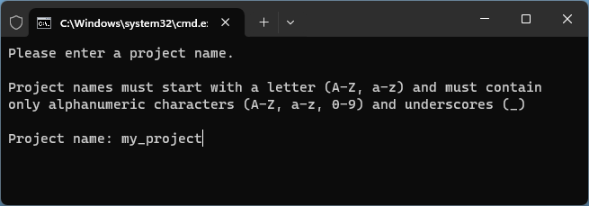
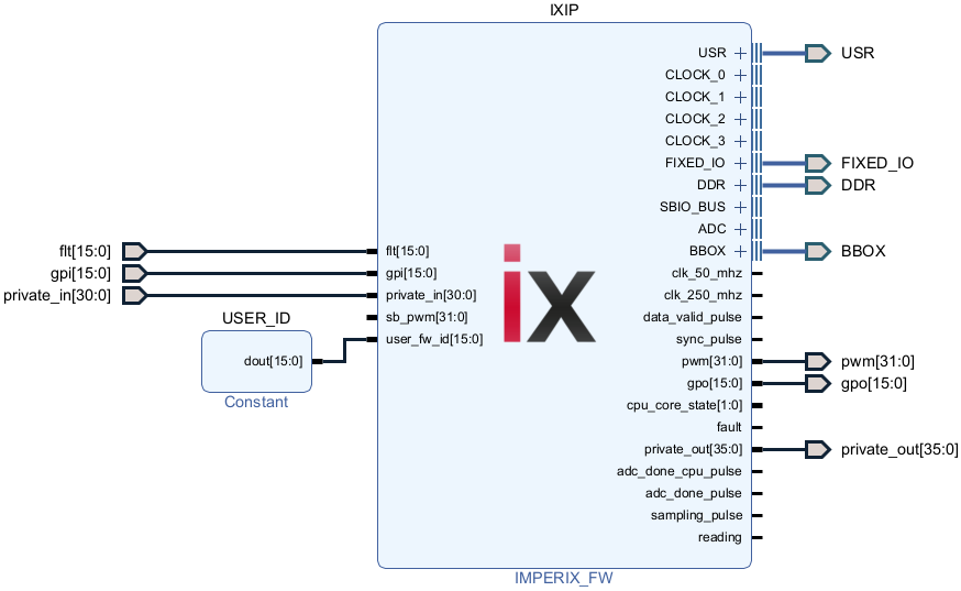
A new Vivado instance will launch and execute the Tcl script to reconstruct the sandbox template project environment from scratch. The project contains the mandatory imperix firmware IP (IXIP) and the optional AXI4-Stream interface (ix_axis_interface). They are described below.
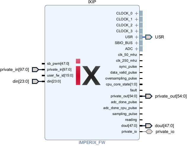
The imperix firmware IP contains the proprietary FPGA logic and provides various interfaces that enable the user to retrieve ADC measurement results, exchange data with the CPU through the SBIO_BUS, drive the PWM from the sb_pwm port, etc.
Further documentation is available in the product guide of the imperix firmware IP.
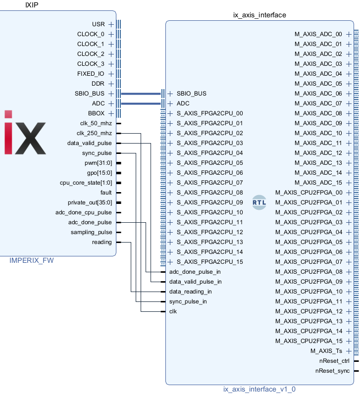
The template includes an AXI4-Stream interface to enable interconnection with a broad range of IPs or user-developed algorithms using High-Level Synthesis (HLS) tools such as Vitis HLS or Model Composer.
This optional interface was made specifically to facilitate implementing a control algorithm in FPGA. It can be deleted from the project without impacting the core functionality of the imperix IP.
Documentation on the AXI4-Stream interface is available in PN126 (retrieving ADC measurements) and in PN128 (exchanging data between CPU and FPGA).
Generating the bitstream and loading it to the target
A “Hello World” example is used to illustrate how to add logic to the template, generate a bitstream, and deploy it to the target controller. In this example, the raw 16-bit ADC measurement is retrieved from the FPGA and transferred to the CPU using an SBI register:
First, create the sandbox template.
- Download the sandbox sources from the FPGA sandbox download page.
- Follow the procedure above to create the Vivado sandbox template project.
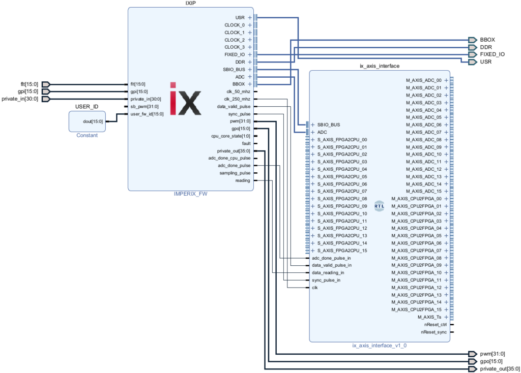
Then, remove the AXI4-Stream interface as it is not used in this example.
- Click on ix_axis_interface.
- Press Delete.
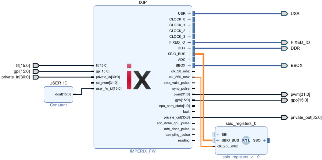
Add an sbio_registers module to the design. This helper module allows exchanging 16-bit registers with the CPU using the SBI (SandBox Input) and SBO (SandBox Output) blocks. It is further documented in PN128 (which covers the exchange of data between CPU and FPGA).
- Navigate to File → Add Sources…
- Select Add or create design sources. Click Next.
- Click Add Files, select sbio_registers.vhd from the
hdlfolder, and click Finish. - Drag and drop sbio_registers from the Design Sources folder to the block design.
- Connect it to the IXIP as shown in the image below.
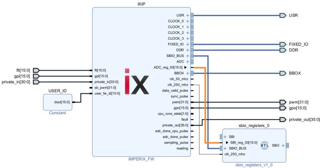
Connect the ADC measurement of channel 0 to the SBI register 0.
- Expand the ADC and SBI interfaces.
- Connect ADC_reg_00 to SBI_reg_00.
Generate the bitstream, which is the “compiled” result of the FPGA design. It contains the configuration mapping that will be loaded onto the target controller to define its hardware logic.
- Navigate to Flow navigator (left bar)→ PROGRAM AND DEBUG.
- Click Generate Bitstream.
This will launch the synthesis, implementation, and bitstream generation processes. Depending on the complexity of the design and the computer’s performance, this may take anywhere from a few minutes to over half an hour. Once the bitstream is generated, verify that it meets the timing requirements.
- Navigate Window → Project Summary.
- Verify that the Timing numbers are all positive.
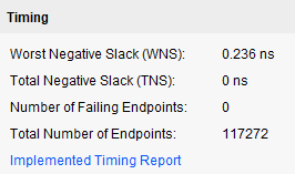
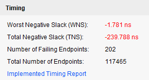
Failure to achieve timing closure may result in unpredictable FPGA firmware behavior. For best practices, refer to the AMD Xilinx design methodology guide.
If the timing requirements are met, load the customized bitstream onto the target.
- Click on File → Export → Export Bitstream File to save the bitstream on the computer.
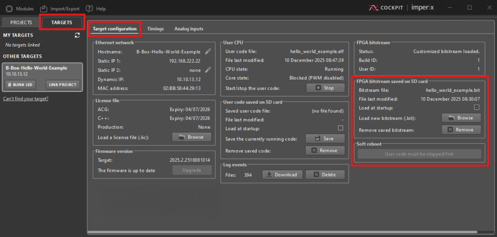
- From Cockpit, navigate to TARGETS → Target configuration.
- In the FPGA bitstream area, click on Browse and load the new bitstream on the target.
- Power cycle the target for the customized bitstream to be loaded.
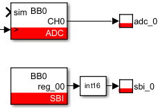
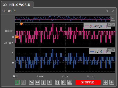
As illustrated below, the bitstream is tested by comparing the result from an ADC block (configured with a sensitivity of 1.0 and an offset of 0.0) with the SBI block. Observing both signals in the Cockpit Scope module confirms that the waveforms have the same shape, but their amplitude differs. The difference exists because the scaling required to convert the int16 data into physical units has not yet been applied. This conversion is documented in PN126.
Opening a project provided by imperix
Sharing Vivado projects often leads to issues, such as missing file references or version mismatches. To prevent these errors, imperix provides examples as Tcl scripts. These scripts contain the necessary commands to automatically reconstruct the project on any machine. This section shows the process of opening and reconstructing Vivado projects provided by imperix.
The aurora_ix_plexim_gen_scripts.zip archive from the page Aurora link with Plexim via SFP is used as an example for the following procedure. It contains two folders:
- The hdl folder contains the source files specific to the example.
- The scripts folder contains the project creation scripts.
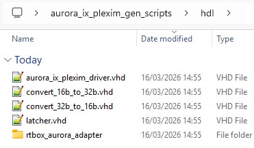
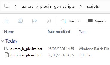
The procedure to reconstruct the Vivado project is the following:
- Download the source FPGA_Sandbox_template_*.zip archive from the download page.
- Unzip it and save the content somewhere on the PC.
- Rename the folder to something more explicit.
- Download the project-specific generation scripts on the page of interest in the Knowledge Base (e.g., aurora_ix_plexim_gen_scripts.zip mentioned above).
- Unzip it and open it.
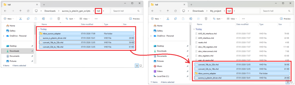
- Copy-paste the content of each subfolder into the corresponding subfolder of the source files.
In this example:- Copy the content of
.../hdl/intoMy_project/hdl/ - Copy the content of
.../scripts/intoMy_project/scripts/
- Copy the content of
- Open <source files>/scripts/<script_name>.bat using a text editor. Ensure the
vivado_pathvariable matches the Vivado version installed on the PC.
- Double-click on the newly copied <source files>/scripts/<script_name>.bat file. If a Windows Defender SmartScreen warning appears, click More info and select Run anyway to proceed.
- Enter a project name and click Enter.
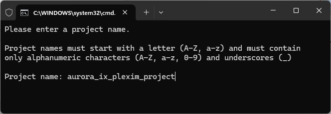
A new Vivado instance will launch automatically and execute the Tcl scripts to import the HDL sources, configure the IP cores, and reconstruct the project environment from scratch.
Going further with FPGA programming
The following pages detail essential aspects of FPGA development on imperix controllers. These include retrieving ADC conversion results as soon as they are available, directly from within the FPGA, exchanging data between the application control code running on the CPU and the logic in the FPGA, and driving the PWM output chain, which consists of a dead-time generation system and the hardware protection mechanisms.
- PN126: Retrieving ADC measurements from the FPGA
- PN128: Exchanging data between the CPU and the FPGA
- PN127: Driving the PWM output chain
Advanced topics
The following pages cover more advanced topics such as observing internal FPGA signals at runtime using ILA (Internal Logic Analyzer) for debugging, accessing the 36 user-configurable 3V3 I/O pins, and configuring the Gigabit transceivers to implement Aurora communication on the SFP ports.
- PN129: Using an ILA to debug an FPGA design
- PN179: Accessing the USR pins in the FPGA sandbox
- PN118: Example of FPGA-based Aurora communication
Automated code generation tools
Traditionally, FPGA designs are implemented using HDL languages such as VHDL or Verilog. However, the user can use automated code generation tools to design FPGA modules without writing a single line of HDL code.
These tools can be separated into two main categories:
- HDL-level tools, such as AMD Vitis Model Composer HDL (formerly System Generator, or SysGen) and MATLAB HDL Coder, allow users to describe their design down to the flip-flop level. These tools are much closer to HDL languages (VHDL or Verilog) and are recommended to implement peripherals such as custom PWM modulators or communication interfaces.
- High-Level Synthesis (HLS) tools, such as AMD Vitis Model Composer HLS (paid Simulink blockset) and AMD Vitis HLS (free C++ alternative), are particularly adapted to describe control algorithms using complex data types and math functions.
Examples
Examples of FPGA-based control algorithms implemented using HLS tools:
- TN142: PI-based current controller for a buck converter
- TN147: FPGA-based control of a grid-tied inverter
- TN133: FPGA-based Direct Torque Control using Vivado HLS
Examples of SFP communication with third-party devices using the Aurora protocol:
- PN110: Aurora link with OPAL-RT via SFP
- PN111: Aurora link with Plexim via SFP
- PN112: Aurora link with Typhoon via SFP
- PN122: SFP communication with an RTDS MMC simulator
Example of interfaces with external peripherals through the 3V3 USR pins:

 By Benoît Steinmann • August 13, 2021 • PN168