
Table of Contents
Imperix controllers provide angle decoder (DEC) resources to decode quadrature-encoded signals produced by incremental encoders, which are widely used in motor drive applications. At the hardware level, DEC inputs are available on pins that are shared with GPI pins.
These inputs can be configured as either four independent inputs or two differential DEC inputs. Each decoder module counts all 4 edges of the A and B inputs, resulting in an angular resolution that is 4 times higher than the PPR value usually specified for a given encoder. The position counter can be reset either to a specified value or using the sensor’s Z signal. The decoded position is latched simultaneously to ADC inputs.
Practical advice for using the DEC modules is provided in PN104.
Simulink block
Signal specification
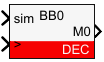
- The output signal is the decoded angle in radians.
- The
siminput signal is used in simulation and represents the actual angle value in radians, computed by the simulation plant model. - The
>input signal needs to be connected to the CONFIG block to account for the exact sampling instant in simulation.
Parameters
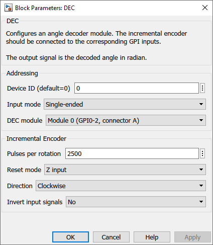
Device IDselects which B-Box/B-Board to address when used in a multi-device configurationInput modeselects if the decoder considers one GPI input per encoder signal (Single-ended) or two GPI with complementary signals (Differential).DEC moduleselects which GPI inputs are used. See the B-Box datasheet or B-Board datasheet to check where to connect the encoder signals.Pulses per rotationdefines the number of pulses of the A or B signal per complete rotation of the encoder, as specified by the manufacturer.Reset modeselects the counter reset mode. If Z input is selected, the pulse counter value is reset on the rising edge of the Z signal. If the maximum value is selected, it is reset as soon as it reaches the number of pulses per rotation.Directiondefines when A is leading B, if the angle increases (Clockwise) or decreases (Counterclockwise).Invert input signalsconfigures the decoder to consider the inverted logical value of the considered GPI inputs.
PLECS block
Signal specification
- The output signal is the decoded angle in radians.
- The target inport (only visible at the atomic subsystem level) is used in simulation and represents the actual angle value in radians, computed by the simulation plant model.
- The
>input signal needs to be connected to the ADC output of the CONFIG block to account for the exact sampling instant in simulation.

Parameters
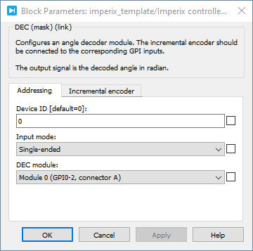
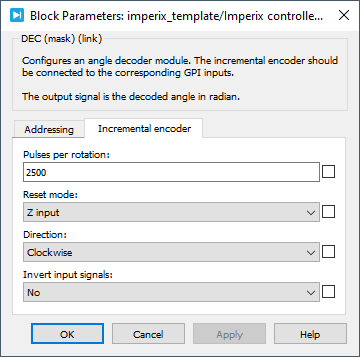
Device IDselects which B-Box/B-Board to address when used in a multi-device configurationInput modeselects if the decoder considers one GPI input per encoder signal (Single-ended) or two GPI with complementary signals (Differential).DEC moduleselects which GPI inputs are used. See the B-Box datasheet or B-Board datasheet to check where to connect the encoder signals.Pulses per rotationdefines the number of pulses of the A or B signal per complete rotation of the encoder, as specified by the manufacturer.Reset modeselects the counter reset mode. If Z input is selected, the pulse counter value is reset on the rising edge of the Z signal. If the maximum value is selected, it is reset as soon as it reaches the number of pulses per rotation.Directiondefines, when A is leading B, if the angle increases (Clockwise) or decreases (Counterclockwise).Invert input signalsconfigures the decoder to consider the inverted logical value of the considered GPI inputs.
 By Simon Strobl • November 8, 2021 • SD100
 By Benoît Steinmann • April 2, 2021 • SD013
 By Julien Orsinger • March 29, 2021 • PN104