Table of Contents
The incremental encoder interface (INC) block decodes the A, B, Z signals from an incremental encoder for motor drive applications.
The B-Box supports up to two differential incremental encoders through the Motor Interface for B-Box RCP. These devices provide two signals in quadrature (usually called A and B), as well as an optional reset line (usually called Z). The decoder module counts all 4 edges of the A and B inputs, leading to an angular resolution 4 times superior to the PPR value usually specified for a given encoder. The position counter can be reset either at a specified value or using the Z signal provided by the sensor. Finally, the position is latched similarly and simultaneously to the sample-&-hold feature of the ADC inputs.
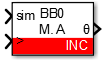
Simulink block
Signal specification
- The output signal is the mechanical angle in the range [0; 2π].
- The sim input signal is used in simulation and represents the actual angle value in radian, computed by the simulation plant model.
- The
>input signal needs to be connected to the CONFIG block to account for the exact sampling instant in simulation.
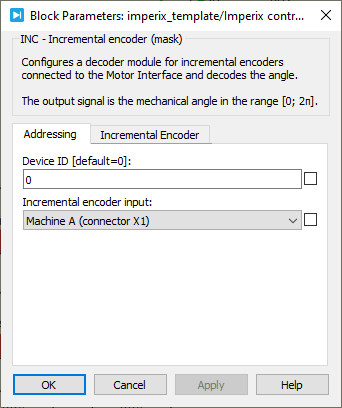
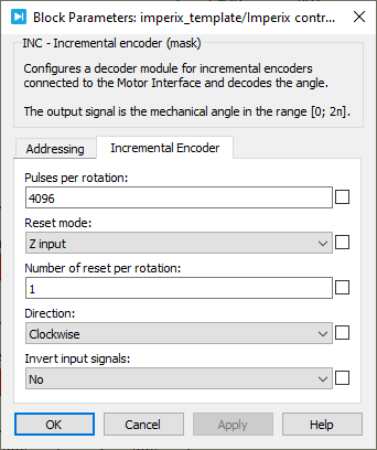
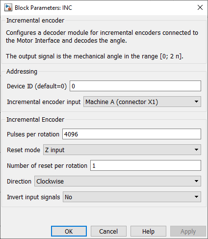
Parameters
Device IDselects which B-Box/B-Board to address when used in a multi-device configuration.Incremental encoder inputselects which connector of the Motor Interface is used.Pulses per rotationdefines the number of pulses of the A or B signal during one complete rotation of the incremental encoder, as given by the manufacturer.Reset Modeselects the counter reset mode. If Z input is selected, the pulse counter value is reset on the rising edge of the Z signal. If maximum value is selected, it is reset as soon as it has reached the number of pulses per rotation.Number of pulse per rotationconfigures the number of Z pulses per complete rotation of the encoder, as given by the manufacturer. It can only be used if the ZINPUT reset mode is selected.Directiondefines if an increasing angle corresponds to a clockwise or counterclockwise rotation.Invert input signalsconfigures the decoder to consider the inverted logical value of the considered digital inputs.
PLECS block
Signal specification
- The output signal is the mechanical angle in the range [0; 2π].
- The sim input signal is used in simulation and represents the actual angle value in radian, computed by the simulation plant model.
- The
>input signal needs to be connected to the CONFIG block to account for the exact sampling instant in simulation.

Parameters
Device IDselects which B-Box/B-Board to address when used in a multi-device configuration.Incremental encoder inputselects which connector of the Motor Interface is used.Pulses per rotationdefines the number of pulses of the A or B signal during one complete rotation of the incremental encoder, as given by the manufacturer.Reset Modeselects the counter reset mode. If Z input is selected, the pulse counter value is reset on the rising edge of the Z signal. If maximum value is selected, it is reset as soon as it has reached the number of pulses per rotation.Number of pulse per rotationconfigures the number of Z pulses per complete rotation of the encoder, as given by the manufacturer. It can only be used if the ZINPUT reset mode is selected.Directiondefines if an increasing angle corresponds to a clockwise or counterclockwise rotation.Invert input signalsconfigures the decoder to consider the inverted logical value of the considered digital inputs.