Table of Contents
The GPO block, or its equivalent C++ routines, is responsible for asserting the specific logic states of the General Purpose Outputs (GPO) pins. This interface allows imperix’s programmable controllers to drive external signals effectively.
Hardware specifications, including location, voltage logic levels and output counts, are summarized in the reference table below. Detailed specifications regarding the GPO can be found within the associated product datasheet. Additionally, a comprehensive technical comparison of imperix’s programmable controllers is provided in PN250.
| Param. | B-Box 4 | B-Box 3 | B-Box micro | B-Board 3 PRO |
|---|---|---|---|---|
| Location and count | – 48x fiber/VHDCI outputs | – 16x VHDCI outputs | – 8x PCB header outputs | – 16x PCB header outputs |
| Logic level | – 3.3V/5V (elec.) | – 3.3V/5V | – 5V | – 3.3V |
| Shared with | – PWM | N/A | N/A | N/A |
| Product datasheet | B-Box 4 | B-Box 3 | B-Box micro | B-Board 3 PRO |
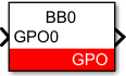
Simulink block
Signal specification
The GPO pin is set if the input is >0.
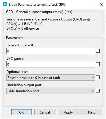
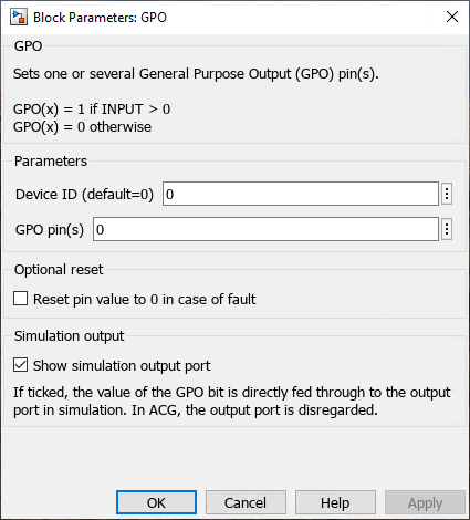
Parameters
Device IDselects which B-Box/B-Board to address when used in a multi-device configuration.GPO pin(s)(vectorizable) is the GPO pin(s) to control. It can be a single value or a vector.Reset pin value to 0 in case of faultacts when a fault is detected, for instance when an analog inputs exceeds a configured limit value.Show simulation output portdefines if the simulation output is displayed or not.
PLECS block
Signal specification
The GPO pin is set if the input is >0.

Parameters
Device IDselects which B-Box/B-Board to address when used in a multi-device configuration.GPO pin(s)Optional resetcan be set toReset pin value to 0 in case of faultto act when a fault is detected, for instance when an analog inputs exceeds a configured limit value.Simulation input port