Table of Contents
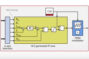
Xilinx Vitis HLS (formerly Xilinx Vivado HLS) is a High-Level Synthesis (HLS) tool developed by Xilinx and available at no cost. Vitis HLS allows the user to easily create complex FPGA-based algorithms using C/C++ code. It supports complex data types (floating-points, fixed-points,…) and math functions (sine, arctan, sqrt,…). It also supports AXI4-Stream to easily exchange data with other IPs.
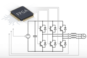
This tools is particularly useful when porting a control algorithm from the CPU to the FPGA of a power converter controller such as the B-Box RCP, the B-Board PRO.
Alternative to Xilinx Vitis HLS
An alternative to Vitis HLS is Model Composer, which provides the same features in a MATLAB Simulink environment. For “lower-level” designs such as PWM modulators, tools such as System Generator or HDL Coder are more appropriate.
Compared to Model Composer, Vitis HLS presents the advantage of being standalone and free of cost. However, Vitis HLS may be more difficult to use, as it requires some C++ skills. Moreover, it is much more tedious to write testbenches for Vivado HLS designs.
Downloading and installing Xilinx Vitis HLS
Xilinx Vitis HLS is installed alongside Vivado, as details in the installing Vivado Design Suite page.
Xilinx Vitis HLS example workflow
This tutorial broadly outlines the main steps required to generate a Vivado IP using Vitis HLS. It is not its purpose to be exhaustive but rather serves as a guideline. It also provides tips for designs targetting imperix controllers. For more detailed information, the user should refer to the Xilinx documentation, such as:
- The High-Level Synthesis Tutorial (xilinx.com)
- Getting Started with Vitis HLS (github.com)
- Xilinx HLS basic examples (github.com)
The sources of this Xilinx Vitis HLS example can be downloaded below.
The tutorial uses a PI-based current control implementation as an example to illustrate the key points of the Xilinx Vitis HLS workflow. It is based on the Forward Euler method, which is presented on the PI controller implementation for current control technical note.
It is highly recommended to read through the high-Level synthesis for FPGA developments page to see how this IP integrates into a complete design. It will help to understand some of the choices made, notably concerning the input and output ports.
Creating a xilinx Vitis HLS project
1. Launch Xilinx Vitis HLS (the following screenshots comes from Vitis HLS 2020.2)
2. Click on Create Project or go to File -> New Project…
3. Enter a project name and hit Next
4. Chose a top function name. This will also be the name of the resulting Vivado IP. Hit Next
5. There is no need to select a testbench file at this stage. Hit Next.
6. Setup the clock period of 4 ns. Select the part xc7z030fbg676-3, keep Vivado IP Flow Target for the Flow Target, and hit Finish.
7. Add sources the C++ source files to the project. In this example, we add the sources PiBasedCurrentControl.cpp and PiBasedCurrentControl.h. These files are available in the zip provided above.


Below is the C++ code of the algorithm used in this example, for reference. Each portion of this code is explained and commented on in the following sections.
Defining the IP input and output ports
The code below defines the inputs and outputs of the IP. We made the following choices:
- Data types:
- The parameters coming from the CPU (
Il_ref,KpandKi) are set as single-precision (float). - The inputs
Il_raw,Vin_rawandVout_rawwill be directly connected to the ADC interfaces and as such must be set as int16. - The input
Tsis a uint32 value holding the sampling time in nanoseconds. - The input
CLOCK_periodis a uint16 value representing the PWM period in ticks. - The output
duty_cycle_ticksis a uint16 value that will be connected to the PWM IP.
- The parameters coming from the CPU (
- Interfaces
- After the user CPU code starts, the
CLOCK_periodinput is constant. Thus its mode is set as ap_none (No protocol). - The
duty_cycle_ticksoutput uses the ap_vld (Valid Port) mode. As shown on the very last image of this page, it will generate an additionnal “valid” portduty_cycle_ticks_ap_vldindicating when theduty_cycle_tickscan be read. - All the other inputs use the AXI4-Stream protocol.
- After the user CPU code starts, the
void PiBasedCurrentControl(hls::stream<int16_t>& in_Vin_raw,
	hls::stream<int16_t>& in_Vout_raw,
	hls::stream<int16_t>& in_Il_raw,
	hls::stream<float>& in_Il_ref,
	hls::stream<float>& in_Ki,
	hls::stream<float>& in_Kp,
	hls::stream<uint32_t>& in_Ts,
	uint16_t in_period,
	uint16_t &out_dutycycle)
{
#pragma HLS TOP name=PiBasedCurrentControl
#pragma HLS INTERFACE axis port=in_Vin_raw
#pragma HLS INTERFACE axis port=in_Vout_raw
#pragma HLS INTERFACE axis port=in_Il_raw
#pragma HLS INTERFACE axis port=in_Il_ref
#pragma HLS INTERFACE axis port=in_Ki
#pragma HLS INTERFACE axis port=in_Kp
#pragma HLS INTERFACE axis port=in_Ts
#pragma HLS INTERFACE ap_none port=CLOCK_period
#pragma HLS INTERFACE ap_vld port=duty_cycle_ticks
#pragma HLS INTERFACE ap_ctrl_none port=return

    // implementation...

}Code language: C++ (cpp)
Implementing the algorithm
The algorithm implemented in this example is the same as the one in the Model Composer introduction. Taking a look at that page may help to understand the algorithm.
The read() method reads one value from an AXI4-Stream. The algorithm starts by reading all the stream inputs. The Ts input is multiplied by 1e-9 to obtain a value in seconds.
int16_t Vin_raw = in_Vin_raw.read();
int16_t Vout_raw = in_Vout_raw.read();
int16_t Il_raw = in_Il_raw.read();
float Il_ref = in_Il_ref.read();
float Ki = in_Ki.read();
float Kp = in_Kp.read();
float Ts_ns = (float) in_Ts.read();
float Ts = Ts_ns * 1e-9f;Code language: C++ (cpp)
The ADC values provided by the starter template are the raw result from the ADC chips. They must be multiplied by a gain to obtain physical values. An example of gain computation is available on the ADC block help page. To simplify the model, the ADC gains are defined as constants and offsets are simply ignored. This example considers the sensor sensitivities of a PEB 8038 module. The user could choose to use tunable parameters coming from the CPU so that the ADC can be tuned in real-time.
// Gains for imperix PEB 8038 half-bridge SiC power module
// with a B-Box frontpanel gain value of x4 for all inputs
const float Gain_Il   = 10/32768*1/(0.05*4); //50 mV/A, x4 frontpanel gain
const float Gain_Vin  = 10/32768*1/(0.00499*4); //4.99 mV/A, x4 frontpanel gain
const float Gain_Vout = 10/32768*1/(0.00499*4); //4.99 mV/A, x4 frontpanel gain

float Il   = Gain_Il   * (float)Il_raw;
float Vin  = Gain_Vin  * (float)Vin_raw;
float Vout = Gain_Vout * (float)Vout_raw;Code language: C++ (cpp)
The integrator of the PI controller acts as an accumulator and, thus, requires that its value is kept in memory between executions. To that end, the static keyword must be used. The HLS RESET pragma specifies that this variable is reset when the IP block reset input pin (ap_rst_n) is asserted.
static float accumulator = 0;
#pragma HLS RESET variable=accumulatorCode language: C++ (cpp)
By design, the duty_cycle ranges from 0.0 to 1.0. Such a narrow range is particularly well-suited for a fixed-point algorithm, as we know beforehand that only a single bit is required for the integer part. We arbitrarily choose a fractional length of 15 bits so we obtain a fix16_15 value. Since the output is a number of ticks, it must be an integer value, and the fractional part is removed by simply transforming the result into a uint16.
#define SAT_LIMIT_HIGH 1.0f
#define SAT_LIMIT_LOW  0.0f

// some code...

float duty_cycle = (Vout + pi_result) / Vin;

if (duty_cycle > SAT_LIMIT_HIGH) {
	duty_cycle = SAT_LIMIT_HIGH;
	saturation = true;
} else if (duty_cycle <= SAT_LIMIT_LOW) {
	duty_cycle = SAT_LIMIT_LOW;
	saturation = true;
}
else
{
	saturation = false;
}
// Width = 16 bits, integer part = 1 bit
ap_fixed<16,1> duty_fixed = duty_cycle;

out_dutycycle = (uint16_t) (duty_fixed*in_period);
Code language: C++ (cpp)
Generating an IP core using Vitis HLS
- Launch the C Synthesis by going to Solution -> Run C Synthesis -> Active Solution

- Once the synthesis is done, export the RTL using the Vivado IP format
- Click Solution -> Export RTL,
- Select the Vivado IP (.zip) format.
- The generated RTL can be VHDL or Verilog, it does not matter.
- Choose an output location, for instance
C:/KB/PN163/Generated/IP
- Click OK.
Performance and resource estimates
The FPGA of imperix controllers (part: xc7z030fbg676-3) possesses 78600 LUT, 157200 FF and 400 DSP, from which around ~30% is used by the imperix firmware IP. By clicking on Solution -> Open Report -> Synthesis, the user has access to the synthesis summary report which estimates the IP latency and resource usage. In this example, Vitis HLS shows the following estimation: 2624 LUT (3.3% of total), 2211 FF (1.4%), and 9 DSP (2.3%).

Adding the IP core in a Vivado project
Here are the steps required to add the example IP generated by Xilinx Vitis HLS into a Vivado project.
- Unzip the file generated by Xilinx Vitis HLS (PiBasedCurrentControl.zip),
- Go in the IP Catalog,
- Right-click and select Add Repository…
- Select the folder containing your unzipped IP (e.g.
C:\imperix\sandbox_sources\my_IPs). This folder can contain multiple IPs. - And finally the IP can be added to a block design like any other Xilinx IP
To see an example where the PI-based current control IP in action please refer to the high-Level Synthesis for FPGA developments page.


