
Table of Contents
This note specifically addresses the configuration and implementation of variable frequency modulation with imperix controllers. More general guidance on configuring basic sampling and modulation timings on these products is provided in PN259.
Working principle of variable frequency modulation
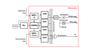
Imperix controllers possess CLK resources that support changing their frequency during runtime. At the hardware level, this is possible for the CLK1, CLK2 and CLK3. More information about the corresponding hardware architecture is given in PN253.
By mapping a PWM resource onto one of these clocks, and modifying the frequency of that clock, variable-frequency modulation can be obtained. This can notably be useful in applications such as resonant converters or in the case of dynamic reconfiguration (start-up of drives, for instance).
CLK1, CLK2 and CLK3 are entirely independent, meaning that more than one variable frequency can be used simultaneously. However, CLK0 cannot be used for that purpose, because this clock is linked to the sampling and control execution, which are desirably solely implemented with a constant frequency.
Importantly, a change in frequency is only applied at the reset of the clock counter. This means that the block always completes the running period before changing its frequency. This slightly reduces the reactivity of the frequency change, but also guarantees a glitch-free transition between frequencies.
Variable frequency with the ACG SDK
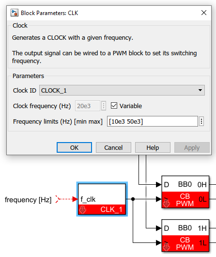
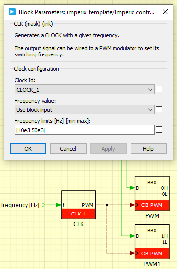
The screenshots below show how to use and configure a CLK block for variable frequency modulation.
Variable frequency with the CPP SDK
As shown in the following code snippet, the frequency change is performed by re-configuring the clock generator CLK1 during control execution. This example uses the following configuration:
| Clock | Linked to | Configuration |
|---|---|---|
CLK0 | Interrupt and sampling | Fixed frequency (50kHz) |
CLK1 | PWM_CHANNEL_0 | Variable frequency |
tUserSafe UserInit(void)
{
  // The interrupt and sampling use CLOCK_0
  Clock_SetFrequency(CLOCK_0, 50e3);
  ConfigureMainInterrupt(UserInterrupt, CLOCK_0, 0.5);

  // The PWM_CHANNEL_0 uses CLOCK_1 which is set as real-time tunable
  Clock_SetFrequency(CLOCK_1, 10e3);
  Clock_ConfigureAsRealTimeTunable(CLOCK_1);

  CbPwm_ConfigureClock(PWM_CHANNEL_0, CLOCK_1);
  CbPwm_ConfigureOutputMode(PWM_CHANNEL_0, COMPLEMENTARY);
  CbPwm_ConfigureCarrier(PWM_CHANNEL_0, TRIANGLE);
  CbPwm_ConfigureDeadTime(PWM_CHANNEL_0, 1e-6);
  CbPwm_SetDutyCycle(PWM_CHANNEL_0, 0.5);
  CbPwm_Activate(PWM_CHANNEL_0);

  Adc_ConfigureInput(0, GAIN_I, 0.0);
  Adc_ConfigureInput(1, GAIN_V, 0.0);

  return SAFE;
}

// Global variables can be observed from Cockpit
float current;
float voltage;
float freq;

tUserSafe UserInterrupt(void)
{
  current = Adc_GetValue(0);
  voltage = Adc_GetValue(1);

  freq = GetOptimizedFrequency(current, voltage);

  Clock_SetFrequency(CLOCK_1, freq);

  return SAFE;
}Related Articles
Architecture of imperix controllers

CB-PWM – Carrier-based PWM

CLK – Clock generators
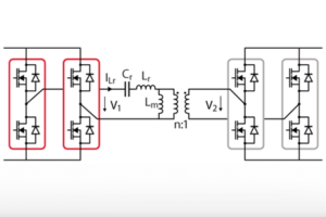
LLC resonant converter for battery charging applications

Timing configuration on imperix controllers
