Table of Contents
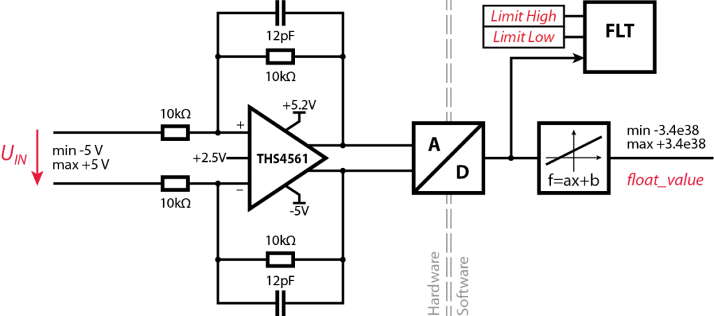
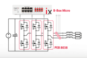
This page covers the configuration of the analog inputs of the B-Box Micro. The B-Box Micro possesses 8 analog inputs with identical channels. The equivalent schematic of the complete data acquisition chain is depicted below.
Since the gain of the input stage is equal to 1, the differential input range of the B-Box Micro is the same as for the B-Board PRO itself, which is ±5V.
Unlike the B-Box RCP, the B-Box Micro does not feature a fully-programmable front-end, which means configurable input impedances, programmable gain amplifiers and low-pass filters are not available. These features of the B-Box RCP are described in Analog front-end configuration on B-Box RCP (PN105). However, the B-Box Micro features FPGA-based safety limits which can be configured on the software side.
The following sections show the two steps that should be taken before turning on the power side:
- First and foremost, the safety limits must be set carefully.
- Then the software blocks should be configrured properly.
Safety limits
The B-Box Micro provides the capability to program safety limits that blocks PWM outputs if one of the analog inputs exceeds the configured limit value. If configured properly, this ensures that dangerous or potentially damaging values (such as current or voltage) cannot be exceeded.
Configuring the safety limits
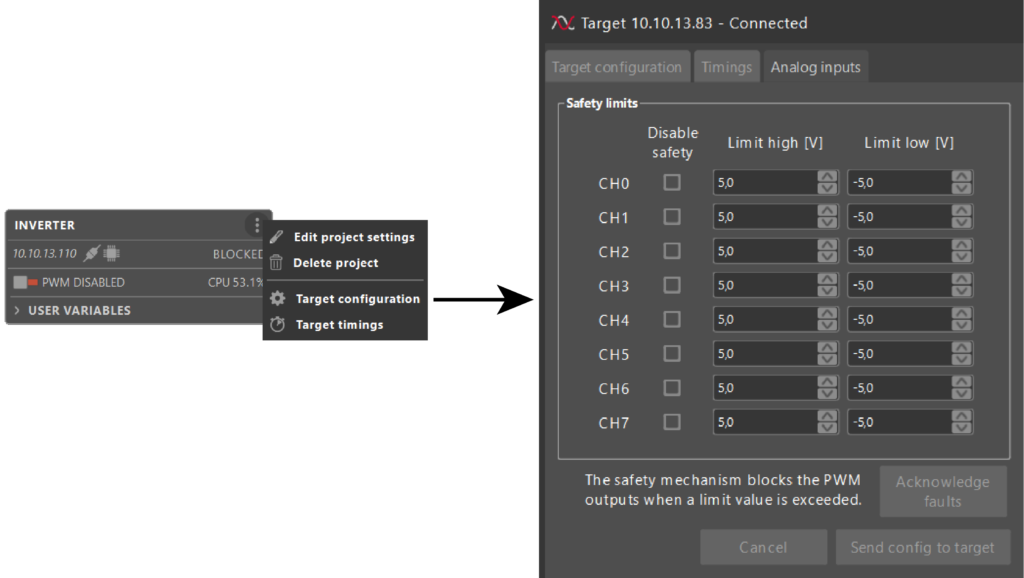
Unlike the B-Box RCP, which implements these protections as a software-independent mechanism, the B-Box Micro relies on programmable FPGA-based comparators, which can be directly configured from within Cockpit. For that, when connected to a B-Box Micro, the Target configuration window offers an additional tab called Analog inputs (see illustration below).
The selection of suitable limit values used as protection thresholds is always a function of the application. It is generally recommended to select limits that are slightly above the planned operating conditions, while staying below the maximum acceptable ratings of the involved components. In some cases, the protection of personnel may also impose lower constraints.
Operating with safety limits
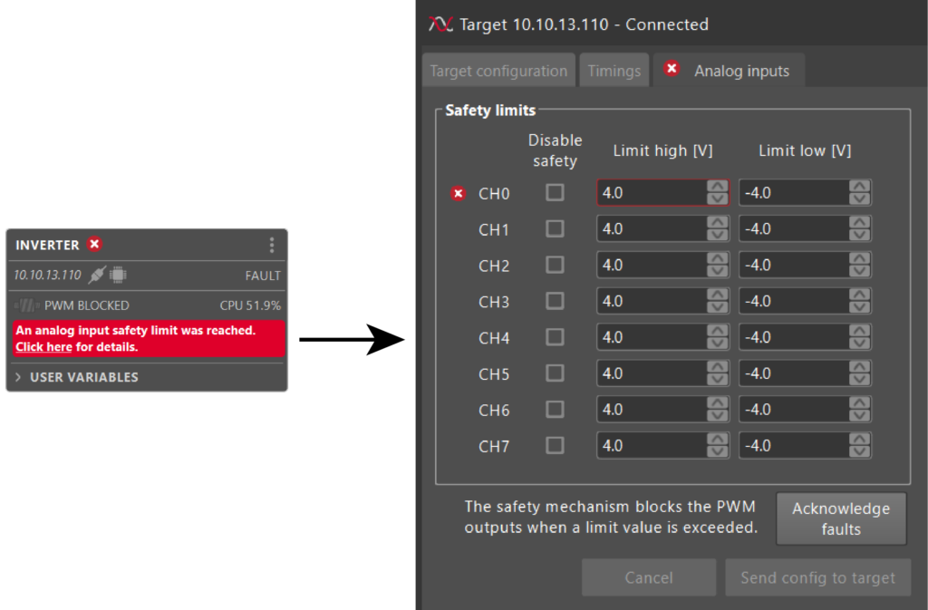
During operation, in case any overvalue is detected, the B-Box Micro enters the so-called FAULT state, which itself leads to the blocking of all PWM outputs. Cockpit indicates the FAULT state in the project pane interface as shown below. By clicking on the message “Click here for details” Cockpit opens the Target configuration window and shows which limit (high or low) on which channel was exceeded (see illustration below). In order to allow PWM outputs to be enabled again, the fault must be acknowledged by clicking on the corresponding button.
Numerical example
Let’s assume that a sinusoidal current is measured using a DIN50A sensor. It is planned that the system will be operating at most with 18A (RMS), which is compliant with the employed equipment. A reasonable threshold could hence be set at 20A (RMS value), so that any current exceeding that value may be considered as a sign of some sort of malfunction.
The sensor sensitivity being 99.0 mV/A, the Limit high and Limit low values can be computed as follows:
- Maximum acceptable instantaneous current: \(\pm 20\,\text{A}\times\sqrt{2}=\pm 28.28\,\text{A}\)
- Corresponding sensor output: \(\pm 28.28\,\text{A} \times 99\,\text{mV/A} = \pm 2.8\,\text{V}\)
- Limit high \(=+2.8\,\text{V}\) and Limit low \(=-2.8\,\text{V}\)
Software configuration of ADC data acquisition
Simulink blockset
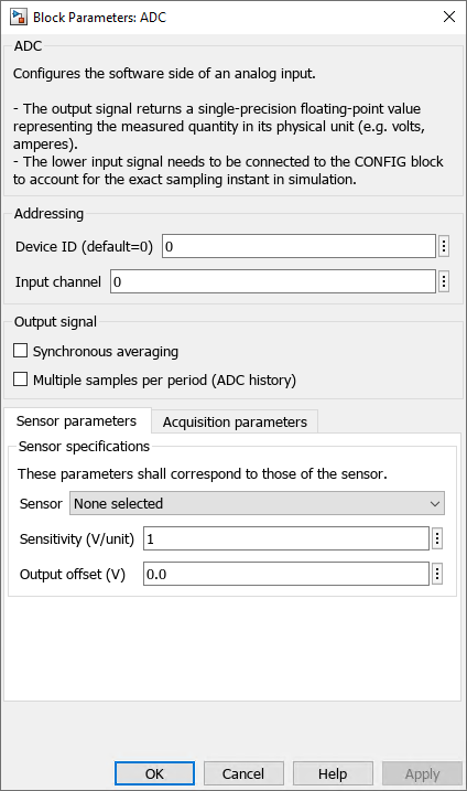
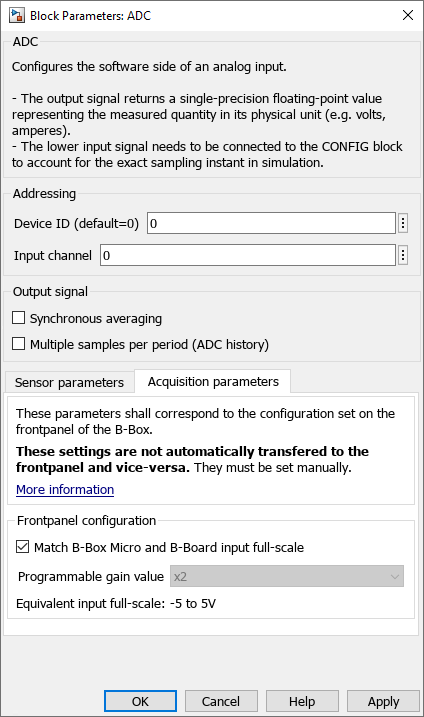
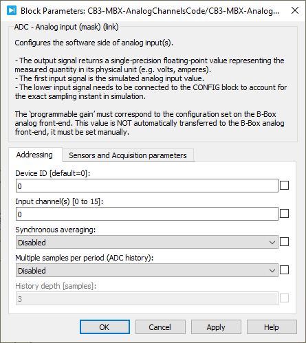
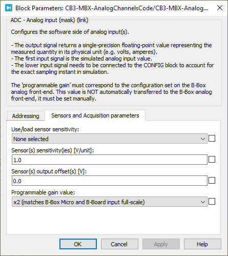
ADC blocks mainly serve to transform the raw 16bits ADC data into a usable floating-point quantity. By configuring the block with the suitable sensor parameters (sensitivity and offset), the computation will be executed automatically using these parameters. When using imperix sensors, the parameters can even be pre-loaded using the related drop-down list.
A third parameter must also be configured for the above-mentioned computation to be correctly executed: the overall gain of the analog input stage. While this is a configurable parameter with the B-Box RCP, this is always fixed with the B-Box Micro. The admissible (differential) full-scale being ±5V, the equivalent gain is x2.
PLECS blockset
The same configuration parameters are accessible from the PLECS blockset, as shown below.
C/C++ configuration
First, during the initialization phase, each ADC channel must be properly configured using Adc_ConfigureInput():
void Adc_ConfigureInput(uint channel, float gain, float offset);Code language: C++ (cpp)channelis the analog input channel number.gainandoffsetmust be configured considering that the returned value during operation is computed as \(y=ax+b\), where \(a\) is the gain and \(b\) the offset.
Numerical example
This example considers the current sensor of a PEB8024 module, which sensitivity S is 50.0mV/A. Considering that the ADC offers 16 bits over the ±5V input range, the gain is computed as follows:
- This results in a total sensitivity of \(\alpha = S \cdot 32768/5=327.68[\text{bit/A}]\).
- In this example,
gainmust therefore be equal to \(a=1/\alpha=3.052[\text{mA/bit}]\).
Alternatively, it is possible to use the Macro ADCONV_BBOARD, corresponding to is 5/32768.
- In this case,
gainmust be set to \(a=ADCONV\_BBOARD/S \).
The offset value can be adjusted empirically to cancel the measured value when no current is flowing through the sensor (static offset).
Subsequently, within each interrupt, the latest value can be retrieved using Adc_GetValue(), in which channel is the analog input channel number:
float Adc_GetValue(uint channel);Code language: C++ (cpp)

