Table of Contents
This note outlines the key considerations for developing a custom user interface specifically for the operation of Imperix power converters. Several possibilities are available to users, such as:
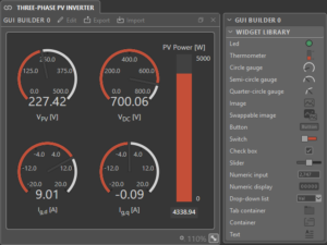
- Using the GUI Builder module directly available in Cockpit.
- Designing a GUI with MATLAB App Designer and the Industrial Communication Toolbox
- Using the open62541 C library and a C++ framework such as Qt or wxWidgets
- Working with Python and Freeopcua with the tkinter package
In this article, the App Designer approach is selected for maximum flexibility. A Graphical User Interface (GUI) for a grid-tied PV inverter is developed as an example, based on advice given in PN130. The GUI itself, as well as the corresponding Simulink model can be downloaded using the following link.
The implementation of such an interface is typically useful in order to manage the run-time execution of a power converter, including for instance:
- Status information (running, stopped, discharge, fault, etc.)
- Real-time measurements (power flows, voltage, current, etc.)
- Fault diagnosis information (log messages, probable causes, etc.)
- Operation set points (current, power, etc.)
- Commands (start, stop, control mode change, etc.)
Accessing system and user variables from a custom user interface
Starting with a small reminder on the B-Box RCP’s OPC UA variable might be useful. There are two types of variables in the B-Box RCP: the Imperix system variables and the user-created variables. The system variables provide configuration and status information about the target. For the user-created variables, when a user code is started, an OPC UA variable is created for each probe variable and tunable parameter present in the user model (Simulink, PLECS or C++). More information on the topic can be found on the page: OPC UA: the communication protocol for industrial automation applications.
Converter automation
Designing a custom user interface usually translates the desire to automate and simplify the operation of a given system. The two following sections will present how to automatically launch a user code upon powering the B-Box RCP and how to implement a state machine to automate the starting procedure of the power converter.
Launch a user code on start-up
It must be noted that actions such as loading the user code file or a custom FPGA bitstream file into the target or updating the target firmware cannot be performed using OPC UA. Furthermore, a code must be running on the device for a client to be able to access user variables and operate the converter. The user code can then either be manually launched using the usual procedure or launched automatically when powering the target (see procedure below). To check that the code is indeed running on the target, one can access the User CPU state system variable. This User CPU state variable returns the CPU state which can either be Running or Offline.
To avoid starting Cockpit every time one wants to operate the converter with a custom user interface, it can be interesting to automatically start a user code when turning on the B-Box RCP. To do so, follow the procedure below:
- Launch the user code as usual by pressing Ctrl+B on Simulink or Ctrl+alt+B on PLECS. The Cockpit monitoring software should launch automatically.
- Upload the code on your target by entering its IP address.
- Once the code is running on the target, open the Target configuration window
- Click on Save current code to save the current code on the SD card inside of the B-Box RCP.
- Click on the checkbox Load at startup to automatically launch the code when the B-Box is turned-on.
This will save the control algorithm on the SD card inside the B-Box RCP. Then, when the B-Box is turned on, it will automatically load and start the code from the SD card.
Operational state machine implementation
The idea here is to be able to start a power converter by pressing a single button. To do so, a state machine can be implemented to automate the start-up and shut-down procedure of a power converter. This can be especially interesting in the case of grid-tied converters that require switching relays in a precise order to properly connect to the grid.
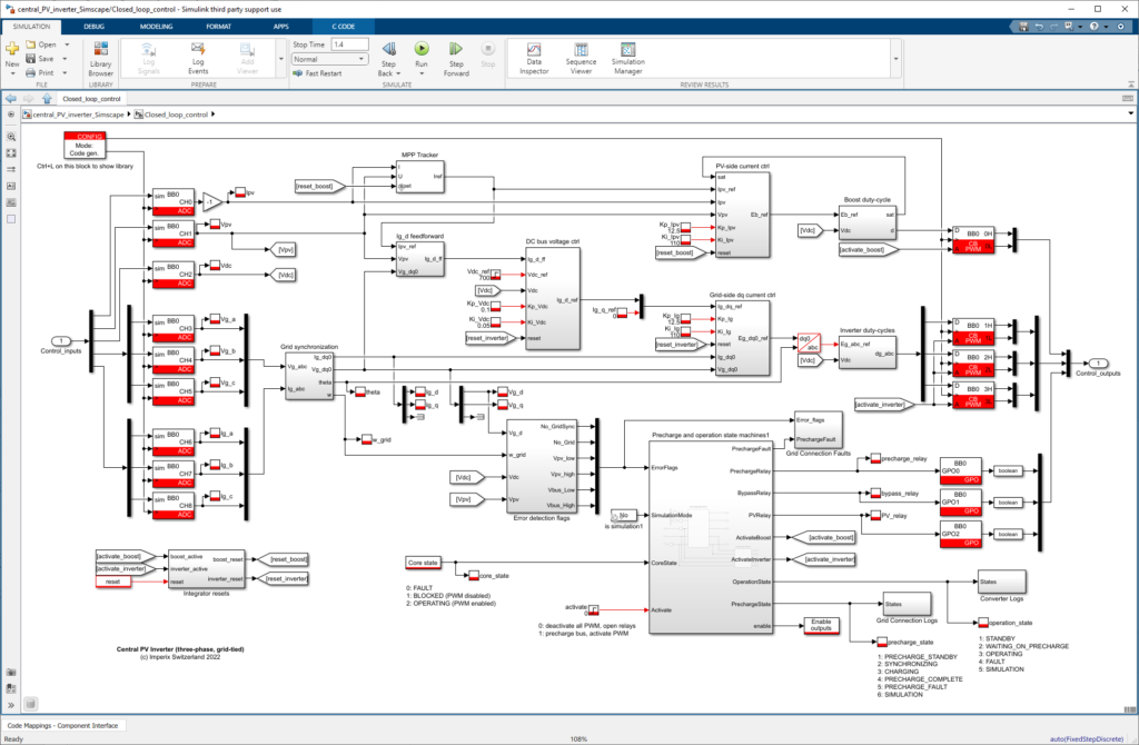
Once the converter is properly started, the PWM signals can be automatically activated using the Enable PWM outputs block. By doing so, Imperix power converter can be up and running with the press of a single button.
Safety considerations when using user interfaces
By nature, custom user interfaces are not proper monitoring tools. As a consequence, the user is less aware of what is happening inside the converter.
Safety considerations then need to be taken even more seriously when operating Imperix converts with a custom GUI. Here is a non-exhaustive list of safety measures that can be implemented:
- Proper configuration of the B-Box analog front-end protection limits (cf. Analog front-end configuration on B-Box RCP).
- Wiring of an emergency push button to the interlock connector of the B-Box.
- Implementation of software error detection mechanism with a dedicated fault state inside the converter state machine. Logging errors with the LOG block could also be useful.
Custom user interface example
In this section, a custom GUI designed for the operation of a grid-tied three-phase PV inverter is given as an example. This GUI was developed using Matlab App Designer. The Simulink model for this example implements an operation state machine, software error detection and logging, and automatic PWM activation. Both the application and the model can be downloaded using the link at the top of the page.

The list of OPC UA user variables is given in the table below:
| Name | Data type | Description |
| Vpv | Single | PV voltage [V] |
| Ipv | Single | PV current [A] |
| Vdc | Single | DC bus voltage [V] |
| Vdc_ref | Single | DC bus voltage reference [V] |
| Vg_a / Vg_b / Vg_c | Single | Grid voltage (phase A B and C) [V] |
| Ig_a / Ig_b / Ig_c | Single | Grid current (phase A B and C) [A] |
| theta | Single | Grid angle [rad] |
| w | Single | Grid angular frequency [rad/s] |
| Vg_d / Vg_q | Single | Grid voltage in dq [V] |
| Ig_d / Ig_q | Single | Grid current in dq [V] |
| Kp_Vdc / Ki_Vdc | Single | PI gains for DC bus controller |
| Kp_Ipv / Ki_Ipv | Single | PI gains for PV current controller |
| Kp_Ig / Ki_Ig | Single | PI gains for grid current controller |
| precharge_relay | Single | The relay used to precharge the DC bus |
| bypass_relay | Single | The relay used to connect to the grid |
| PV_relay | Single | The relay used to connect the PV panel |
| precharge_state | Single | State of the precharge state machine |
| operation_state | Single | State of the operation state machine |


