Table of Contents
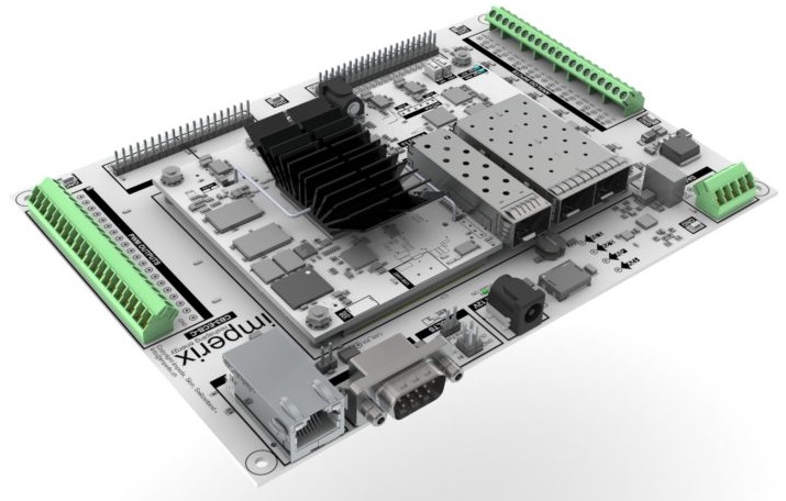
This document is primarily intended for electronic board designers wishing to integrate the B-Board PRO into their designs. It essentially serves as documentation for the Eval-Board marketed by imperix and describes the implementation of the various components and functions it offers. Some additional functionalities that are not present on the Eval-Board are also detailed. To facilitate the reading of this document and the integration of the B-Board PRO into customer designs, the following documents and resources are made available:
| Documents | File type | Version |
|---|---|---|
| Eval-Board schematics | D1 | |
| Eval-Board Altium Designer project (Schematics and PCB) | ZIP-Altium | D1 |
| Altium libraries for JX1, JX2, JX3 connectors | IntLib – Altium | |
| 3D mechanical drawing of the B-Board PRO | STEP A14 | |
| 3D mechanical drawing of the Eval-Board | STEP A14 | |
| B-Board PRO datasheet |
Mechanical considerations
Dimensions and positioning
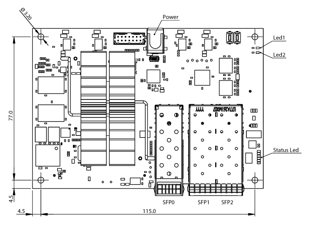
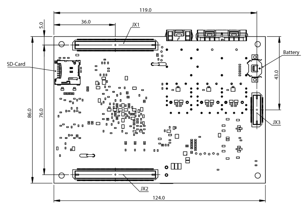
The B-Board PRO is 124mm (4.88”) long by 86mm (3.39”) wide. The maximum height above the carrier board is 22.8mm. The distance between the carrier board and the B-Board is 5mm ( 0.197”). The B-Board is usually mounted using four M3 x 5mm spacers. These can be screwed (e.g. 971050324 Würth Elektronik) or soldered to the carrier board (e.g. 9771050360R Würth Elektronik). In all cases, a clearance diameter of at least 7.5mm around the spacers must be observed on the baseplate to facilitate mounting. We recommend using metal spacers to ensure a ground connection (GND) to the carrier board. Spacers and connectors (JX1, JX2, JX3) must be precisely positioned on the carrier board (see B-Board-PRO datasheet – Mechanical Data).
When positioning the B-Board on the carrier board, it is important to take care not to place any obstructing components in front of the SFP cages, the battery holder, and the SD-Card slot, to keep them accessible if necessary.
Low-profile components (max 2.5mm) can be placed under the B-Board, except below the battery holder, which requires extra clearance. Any component generating heat should not be placed under the B-Board.
Thermal management
The cooling of the B-Board can be either passive (natural convection), or active (ventilation). Under normal operating conditions and with ambient temperatures below 50°C, passive cooling is generally sufficient. In the event of a high CPU and/or FPGA load and/or high ambient temperature, forced ventilation may be required. For optimal ventilation, the airflow should be parallel to the cooler fins (in the direction of the B-Board length).
General recommendations for custom carrier board design
The base PCB must be able to be produced with a track spacing of 0.2mm (8mils) or less to meet the routing requirements of the B-Board’s JX1, JX2, and JX3 connectors.
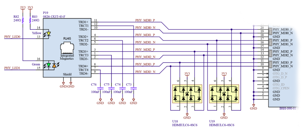
The tracks required for the Ethernet connector (P19 on the carrier board) must be differential pairs with 100Ω impedance. These tracks require careful routing, especially if the Ethernet RJ45 connector is far from the B-Board.
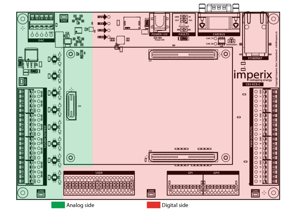
To ensure good quality of the analog signals, analog components should be placed close to the JX3 connector and away from digital components. The ground plane on the analog side should never be used as a return path for digital signals or digital power supplies. Power supplies should preferably be placed close to connector JX2 (on the Eval-Board the power supplies are on the JX1 side for historical reasons).
Mating connectors
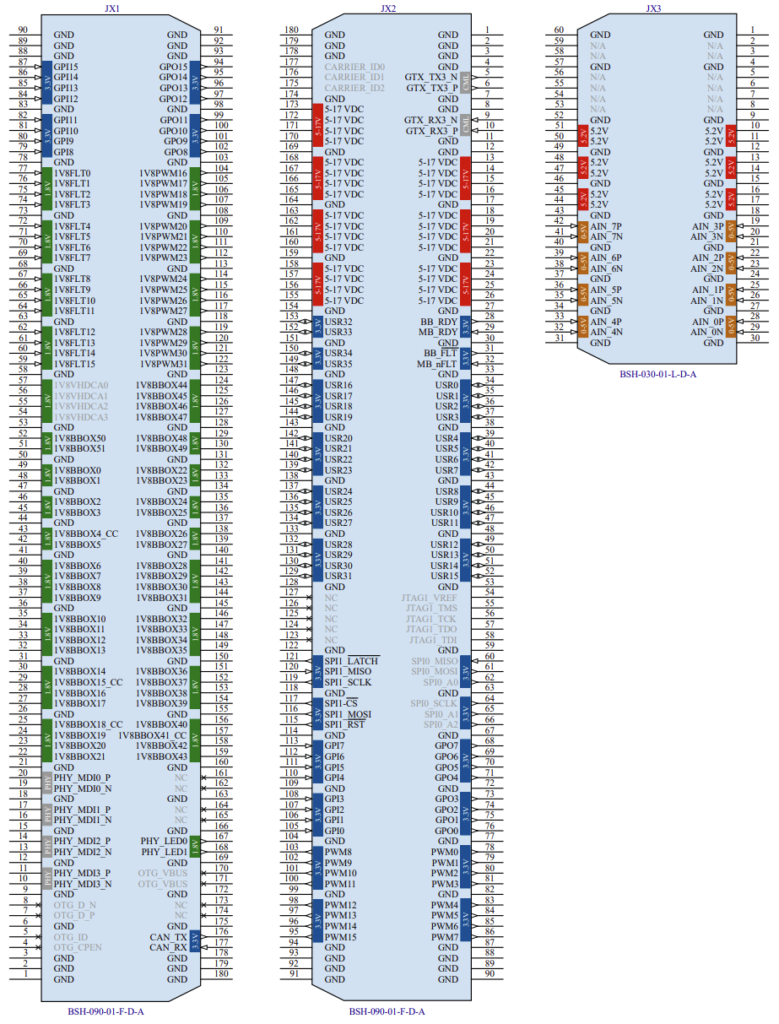
The B-Board connects to the carrier board with three connectors, JX1, JX2, and JX3. The corresponding mating part numbers to be placed on the carrier board are:
- JX1 and JX2: Samtec BSH-090-01-F-D-A
- JX3: Samtec BSH-030-01-L-D-A
An Altium library “BBoard-PRO_Connectors.IntLib” is available to facilitate the implementation of these connectors.
Remarks about connectors:
- If the B-Board analog inputs are not used, the JX3 connector becomes optional, as the spacers are generally sufficient to provide sufficient support.
- Signal names, pin numbers, directions, and voltage levels are indicated in the collapsible section below.
- Signals marked in gray are for internal use only. They cannot be used in third-party designs.
- Signals with a _P or _N suffix must be routed as differential pairs. For these signals, an impedance control is required.
- Signals with the suffix _CC can be used as clock inputs for the FPGA.
Power supplies
The B-Board requires a power supply via its connector JX2. This single power supply is then locally declined into the various required voltages. The B-Board accepts power supply voltages ranging from 4.5V to 17V and consumes a typical power of 7.5W. The power dissipated by the B-Board can, however, be much higher, depending on the software and peripherals connected, but at most 32W. A 12VDC, 1A power supply is a good starting point. Naturally, this power supply can also be used to power the base PCB peripheral circuits, in which case additional power is required. The mains adapter provided with the Eval-Board delivers 12V and 2A (24 W).
On the carrier board, auxiliary power supplies are often required for the digital circuits of the various peripherals implemented (e.g. 3.3V, 5V, or 1.8V). The chip U12 (LM436x0) used on the Eval-Board, is an example of a circuit that can be easily configured to produce these different voltages, with an available current of 1A or 2A.
If the B-Board ADCs are used, a separate dedicated power supply is required. This power supply must be 5.2V and noise-free. This supply feeds the B-Board internal voltage reference, which is exactly 5.0V. For this reason, a power supply slightly higher than 5V is required to ensure the correct operation of the analog circuits and to avoid any saturation effect (see B-Board datasheet). Imperix recommends a voltage between 5.15V and 5.3V. External analog circuits used for signal conditioning can also be powered from this supply. The chip U11 (LM317KTTR) found on the Eval-Board provides a low-noise 5.2V power supply. The LT3045, ADM7170 or ADP7118 circuits are also good compromises for low-noise analog supply.
A low-noise negative supply is sometimes required for analog signal conditioning. On the Eval-Board, an isolated DC/DC converter (U13) is used to generate a negative voltage. In this case, power supply filtering is required to reduce the noise induced by the DC/DC converter. A negative LDO regulator (e.g. LT3094 or ADP7182) can be used to reduce noise and improve stability. A cheaper alternative for this power supply is to use an inverting charge pump (e.g. LM27761) or a discrete negative DC/DC converter (e.g. TPS63710).
Power supply sequencing
To prevent any risk of damage, the auxiliary power supplies of the circuits directly connected to the I/O pin of the B-Board must have a control input (ENABLE), authorized by the B-Board’s BB_RDY signal. Conversely, the MB_RDY signal is required to indicate that the auxiliary power supplies of the carrier board are ready. This can be done easily with a pull-up resistor (R41 on the Eval-Board) that sets the MB_RDY signal high as soon as the 3.3V auxiliary supply is active, allowing the B-Board to continue starting up. Power supply sequencing is described in the B-Board datasheet.
B-Board signals and interfacing suggestions
This section is a comprehensive list of all the B-Board signals and provides design suggestions to interface them with a custom carrier board.
ETH – Ethernet connection
The B-Board requires a 1000BASE-T Ethernet connection (IEEE 802.3ab). This Ethernet interface makes communication with the B-Board simple and efficient.
The B-Board is equipped with a Marvell 88E1512-A0-NNP2I000 PHY, which supplies the signals required for the Ethernet interface on connector JX1. According to the 1000BASE-T standard (IEEE 802.3ab), a transformer is required for galvanic isolation and filtering. This transformer can be a discrete element (e.g. Bourns SM51589PL) or, preferably, integrated into the 0826-1X1T-43-F connector (P19), as on the Eval-Board. The LEDs integrated into the Ethernet connector (P19) show signal connection (orange LED) and activity (green LED) on the network.
ADC – Analog inputs
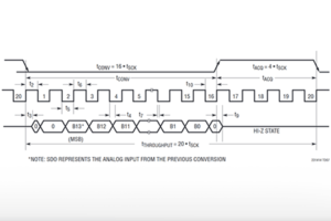
The 8 ADC differential analog inputs are available directly on the JX3 connector. Analog-to-digital conversion is performed by an LTC2324CUKG-16#PBF embedded on the B-Board. The signal can be sampled at up to 2Msample/s with a signal-to-noise ratio of 82dB.
Analog signals must be shaped to meet the requirements of the B-Board analog inputs (+/-5V differential, 2.5V common mode, see B-Board PRO datasheet). A wide variety of analog inputs exist (single-ended, differential, bipolar, unipolar, etc.). In particular, on the Eval-Board, the chips U3 to U10 (THS4551) enable differential input with a gain of 1, and its common mode output is set to 2.5V by U14 and U2 (U2 is the DAC but in the Eval-Board it also provides the 2.5V reference). Protections may be required on the analog lines, particularly when the inputs are connected to external devices (e.g. voltage/current sensors).
It is possible to place additional A/D converters on the carrier board. In this case, they will be interfaced with the B-Board using a few USR[0..35] pins. Implementation examples are detailed on the following pages:
If the number of ADC ports should be extended by the same type of A/D converter that is already on B-Board (LTC2324CUKG-16#PBF), please get in touch with our support team ([email protected]) to get access to the necessary firmware source files.
DAC – Analog outputs
Analog DAC outputs require an external D/A converter (U2 AD5685RBCPZ on the Eval-Board) which uses the dedicated interface used by the B-Board in the B-Box RCP (SPI1). A gain of 2 is provided by an operational amplifier (U1 OPA4205APWT). The output voltage is therefore in the range +/- 5V.
It is important to note that this interface (SPI1) is dedicated to this function only. It cannot be used for any other function developed by the user. If other analog outputs are required, a dedicated device must be implemented and interfaced with the FPGA Sandbox using other digital I/Os as explained in this section.
GPI – Digital input
The 16 GPI digital inputs accept 3.3V signals. They are directly available in the user CPU code with a GPI block or in FPGA Sandbox as gpi[0..15]. On the Eval-Board, only the first eight GPIs are available. These are held in state 0 by pull-down resistors R54 and R55. In general, it is recommended to use positive logic and pull-down resistors to set the inactive state.
GPO – Digital output
The 16 GPO digital outputs provide 3.3V signals. They are directly available in the user CPU code with a GPO block or in FPGA Sandbox as gpo[0..15]. On the Eval-Board, only the first eight GPOs are available. As a general rule, it is strongly recommended to set pull-downs (R56, R57 on the Eval-Board) to maintain these outputs at zero state during the start-up and configuration phases.
USR – Digital I/O
The 36 USR digital inputs/outputs operate at 3.3V. They are available in the Sandbox as USR_tri_io[0..35]. All of them are available on the Eval-Board. These inputs/outputs can be used to interface all kinds of peripherals, but require specific B-Board programming. Further information is available in the FPGA firmware IP documentation.
1V8BBOX – Digital I/O
The 52 1V8BBOX digital inputs/outputs operate at 1.8V. They are available in the Sandbox as bbox_in[x] and bbox_out[x]. They are not available on the Eval-Board and are used internally by the B-Box RCP. They can also be used on third-party products with some restrictions. Please get in touch with [email protected] for further information.
PWM – Pulse Width Modulated signals
There are 32 PWM outputs on the B-Board. On the Eval-Board, only PWM[0..15] are available. These signals are in 3.3V.
Conversion to optical signals may be necessary, for example, to interface with imperix power modules. In this case, we recommend the FT50MHNR optical converter circuit from Firecomms. When other power products are used, conversion from 3.3V (or 1.8V) to a higher voltage (e.g. 15V) may be necessary. A possible implementation is to perform a first conversion to 5V (see section: Digital signal conversion) and then, for example, use a CMOS CD4504B circuit to obtain 15V outputs.
Imperix always works in positive logic when interfacing with power elements. A signal in state 0 is always an inactive signal (switch off).
This inactive state must be maintained not only during the start-up, shut-down, and programming phases but also in case of partial loss of power supplies.
1V8FLT – Fault feedback signals
The 16 FLT digital inputs accept only 1.8V signals. They are available in the user CPU code using the FLT block, or in the FPGA Sandbox as flt[0..15]. These signals are not available on the Eval-Board.
These inputs enable a peripheral to report a fault to the B-Board. This mechanism can be used, for example, for gate driver faults. These signals are linked to the fault management block (FLT), but can also be used as digital inputs from the application software.
Interlocking signals
Fault inter-locking allows coordinating emergency mechanisms between the B-Board and other devices or appliances, or across several B-Boards or systems. These mechanisms are bi-directional as they can inform other devices about an internal fault condition or, reciprocally, receive external trigger signals.
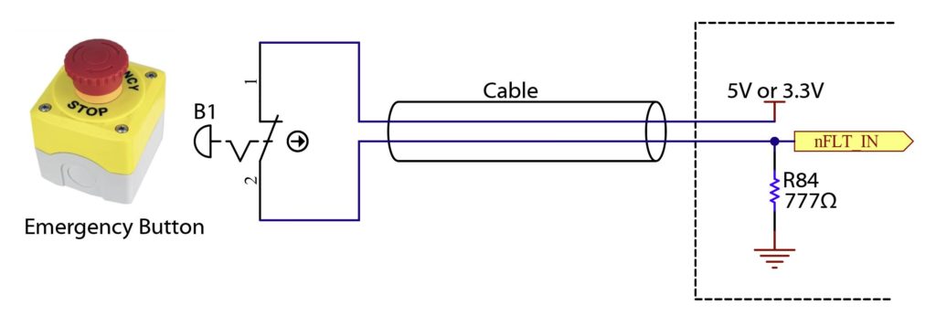
The nFLT_IN signal is active-low. On the Eval-Board, for increased equipment safety, the signal is kept low (active) by default with the pull-down resistor R84. It is therefore necessary to pull this signal high (3.3V or 5V) to get out of the fault condition.
One possible use of this function is to place an emergency stop button between the 3.3V and the nFLT_IN input, ensuring that the button has a normally closed contact (NC). When the emergency stop button is pressed, the button contacts open, forcing the nFLT_IN signal low via the R84 pull-down, signaling a fault. A fault is also generated if the button cable is broken.
On the Eval-Board, this functionality can be disabled by removing the jumper P21. In this case, the signal will be held in state 1 by the B-Board’s existing pull-ups, so no faults will be generated.
CAN
As with the DAC outputs, it is possible to use the existing native functionality of the B-Box by implementing the CAN circuit on the carrier board in the same way as the B-Box.
On the Eval-Board, the CAN bus uses the U17 chip (SN65HVD232DR). This circuit has the advantage of being powered from 3.3V only and fully satisfies CAN-BUS requirements. It is available in different versions: SN65HVD23x or, for a version faster up to 8 Mbps and more robust, the TCAN341x circuit may be a good choice. If galvanic isolation is required, then the ISO1042 circuit may be recommended. On the Eval-Board, the physical output is located on the P10 connector (DB-9), whose pinout is compatible with many USB/CAN converters available on the market (CiA 106 standard Version 1.1.0).
The R36 termination resistor is required for a point-to-point connection (the P20 jumper must be in place). For a daisy-chained connection, the termination resistor is only required at the beginning and the end of the chain.
Fast Serial I/O – GTX
GTX_TX3 and GTX_RX3 signals enable high-speed serial links. Documentation to be completed.
Various digital I/O – User-defined resources
Other communication channels, such as RS485, I2C, SPI, 1-Wire, etc… can be added by programming the B-Board’s FPGA. The USR pins [0..35] can be used for this purpose. If a large number of digital inputs/outputs are required, pins 1V8BBOX[0..51] can also be used as I/Os, pins 1V8FLT[0..15] can be used as additional inputs, and pins PWM[8..15] can be used as additional outputs. Further information on programming the B-Board is available here on FPGA programming.
Digital signal conversion – Voltage translator
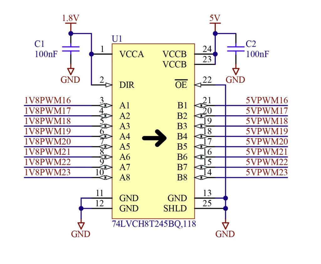
Voltage conversion of digital circuits from 1.8V, 3.3V, or 5V to 1.8V, 3.3V, or 5V can easily be achieved with SN74LXC8T245 or 74LVCH8T245BQ,118 circuits. These circuits can additionally offer higher current per pin than the B-Board and can ensure protection against external faults that could damage the B-Board. Given its low cost, imperix recommends implementing such a circuit whenever there is any doubt about the direct use of B-Board signals.
Contact details
While every effort was made to guarantee complete and clear documentation, it may contain errors or omissions. If any clarification or modification happens to be required, please get in touch with our support team ([email protected]).
Our sales team ([email protected]) is also available for any inquiry about possible services, such as custom developments or review of your existing design.


