Table of Contents
This page gives an overview of possible variable speed drive (VSD) configurations and how to implement them using imperix solutions. Thanks to a modular approach, imperix power modules allow building various converter topologies according to the customer’s needs. When combined with the B-Box RCP controller, dedicated hardware protections safeguard the system against unexpected fault conditions. Additionally, the Motor Interface for B-Box RCP supports various sensors related to motor applications, such as position or torque measurements. Thus, it is possible to build a complete drive with imperix solutions.
Variable speed drive with a voltage source inverter
Reversible DC source
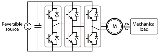
The schematic below illustrates the most simple topology for a variable speed drive: a two-level three-phase voltage source inverter (VSI) supplied by a reversible DC source drives the motor.
The power stage can be built using half-bridge power modules such as the PEB8024 and PEB 8038. At first glance, only the current rating differentiates both modules. However, there are additional criteria to consider for motor applications: the rise and fall times of the semiconductors. Indeed, the power cables of the machines have a parasitic RLC component. Thus, the semiconductors produce a transient over-voltage at every switching event, which may lead to leakage currents flowing through the insulation of the windings (partial discharge). This phenomenon wears out the insulation and shortens the life of the machine. Imperix recommends using PEB8038 modules rather than PEB8024 because their longer rise and fall times result in lower transient overvoltages. Each power module features a set of capacitors on the DC side, as well as built-in measurements of the DC bus voltage and line current. While imperix does not manufacture reversible DC sources, it can provide off-the-shelf power supplies from a third-party manufacturer.
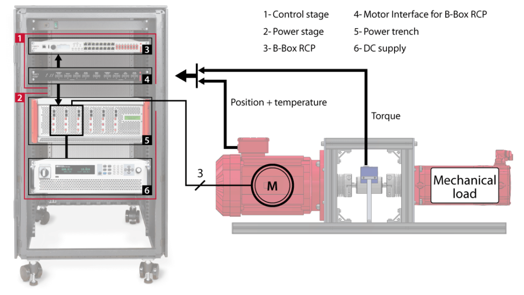
On the control side, the converter is controlled by a B-Box RCP programmable controller. It features dedicated hardware protection circuits linked to its analog inputs. In case an overvoltage or overcurrent is detected, the PWM outputs are immediately disabled and the machine is safely de-energized. The functionalities of the controller can be extended for drive applications by the Motor Interface for B-Box RCP. This interface features extensive connectivity for position, temperature, and torque measurements, as well as all the necessary signal conditioning and power supplies required by these external sensors. The figure below illustrates how the various parts of the variable speed drive can be rack-mounted into a cabinet for ease of use.
Unidirectional DC source
When a machine operates in regenerating mode, part of the braking energy can be recovered and transferred to the DC side. However, if the DC source is unidirectional, this energy will accumulate in the DC bus capacitance and cause its voltage to rise. A braking chopper resistor allows dissipating the excess of power and protects the DC bus against overvoltages. In this case, the topology of the variable speed drive requires an additional power module to connect or disconnect the chopper resistor from the DC bus, as illustrated below.
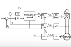
The experimental setup from the TN111 is a typical example using this topology. The device under test is a Permanent Magnet Synchronous Machine (PMSM) driven by a VSI and controlled with a Field-Oriented Control (FOC) technique. Since this method allows regenerative operation of the drive, the DC source has to be either bidirectional or protected by a braking chopper. The Simulink model from the TN111 includes the control of the braking chopper. For PLECS users, a model is available for download in the TN114. Please refer to the AN004 for more details on the braking chopper control.
Variable speed drive with custom active front-end
Off-the-shelf bidirectional DC sources are convenient to supply the DC bus. However, building a custom active front-end (AFE) is also an option. The schematic below presents a possible topology for the AFE: an inverter with an LCL filter replaces the DC source, which results in a back-to-back configuration.
Variable speed drive for a dual-motor testbench
Shared DC bus
A dual-motor testbench provides a convenient platform to validate control techniques for high-performance variable speed drives. The first machine is the device under test (DUT), while the second motor acts as a programmable load. In this case, each machine could have its dedicated power stage and controller. However, the B-Box RCP features enough computational power and I/Os to handle two power stages at once. Additionally, the Motor Interface provides connectivity for two machines. For these reasons, both machines can share a single control stage.
In this type of setup, one machine operates as a motor and drives the other one. Thus, the second machine is in generator mode. If both power stages share the same DC bus, the power circulates in a loop through the DC bus and the shaft. This convenient configuration requires a single DC source to compensate for the losses. The two following figures present the topology of such a variable speed drive and its implementation with the Electric Motor Drive Bundle.
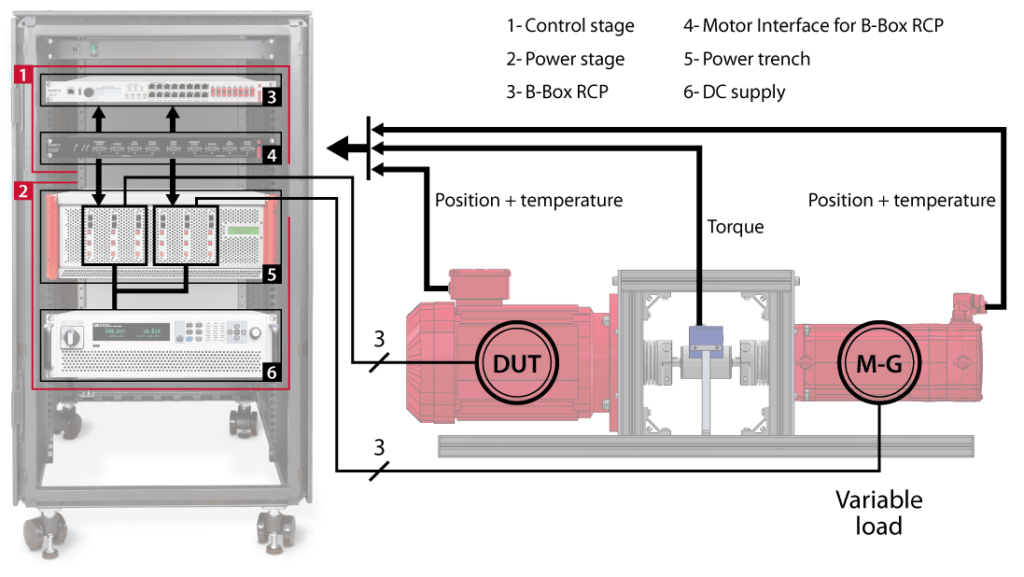
The AN011 presents a dual-motor testbench application where the DUT is the PMSM of an electric car. The drive implements the cascaded speed control presented in TN114 and follows a standardized WLTP speed profile. As for the second machine, it emulates the physics of the car to produce a realistic load torque. The TN138 and TN139 provide more generic examples where the user specifies speed and torque setpoints for the machines.
Custom active front-end with two machines
Sharing the DC bus between the drives is convenient since it only requires a single DC power supply. However, this is not a suitable option if the device under test features an active front-end. Let us consider an example to illustrate the problem. The system presented in the figure below allows emulating a grid-tied wind turbine: the load machine emulates the torque produced by the wind on the shaft. Then, the generator under test converts the mechanical energy into an electrical one. Finally, the AFE transfers the power available at the DC bus to the AC grid.
In terms of power flow, the energy is transferred from the torque source to the AC grid through the following parts: the shaft, the generator, the variable speed drive, and the active front-end. If the machines were sharing the same DC bus, the power would circulate in a loop through the DC bus and the shaft without passing through the AFE. For this reason, the torque source machine requires its own DC bus and supply.
The AN012 explains how to emulate the physics of a wind turbine with the load machine. The generator operates with a sensorless FOC (TN136 and TN137) and implements a Maximum Power Point Tracking (MPPT) algorithm. While the Simulink model from the AN012 uses a shared DC bus topology, it can be adapted to integrate the active front-end from AN005.


