Table of Contents
This technical note presents a possible implementation for the DC voltage control of a power converter. First, the note introduces the general operating principles of cascaded control and then details a possible design methodology. Then, an example of cascaded voltage control for a boost converter is provided. A possible control implementation on the B-Box RCP or B-Board PRO is introduced for both C/C++ and ACG implementations. Finally, simulation and experimental results are compared and discussed.
General principles of cascaded control
Cascaded control is a well-known control strategy, which is often applied to second-order systems (or even of higher-order) that are characterized by the following criteria:
- All state variables can be measured.
- The system can be “decomposed” into first-order systems, whose dynamics (i.e. time constants) are intrinsically rather different. It is generally agreed that an inner loop must be at least 3-4 times faster than its directly “surrounding” loop. In practice, this may possibly be guaranteed by design (component dimensioning).
- Obviously, the inner loop(s) must have a direct impact on the outer loop(s).
- Disturbances impacting the “fast” loop(s) are less severe than those impacting the slower loop(s). This way, cascaded control can achieve its main goal, which is to reject the smaller inner perturbations before they propagate to the rest of the system.
Example of DC bus cascaded voltage control
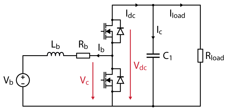
In this note, it is proposed to study the DC bus voltage control of a Step-up boost converter, whose prerequisite is the implementation of a PI controller.
This example features two state variables, namely the inductor current and the capacitor voltage. From a behavioral standpoint:
- The inductor current can be controlled by the voltage \(V_L \).
- The capacitor voltage can be controlled by the current \(I_c \).
General Kirchhoff circuit laws allow us to determine the following equations:
$$ \begin{align}
&R_b I_b + L_b \frac{d I_b}{dt} = V_L = V_b – V_c \\
&C_1 \frac{d V_{dc}}{dt} = I_c = I_{load} – I_{dc} \qquad \text{with} \qquad I_{dc} = \frac{V_b I_b}{V_{dc}} \end{align}$$
In the Laplace domain, this translates into:
$$ \begin{align}
&I_b =\frac{1}{R_b + s L_b} \cdot V_L \\
&V_{dc} =\frac{1}{s C_1} \cdot I_c
\end{align}$$
System-level modeling
An intuitive way to represent the behavior of this circuit is to separate the system into two distinct subsystems, as shown below. This representation also complies with the established system equations.

Plant model
The inductor and the capacitor are modeled as:
$$\begin{array}{ll}
P_1(s) = \cfrac{K_1}{1+s T_1} \quad &\text{with} \quad K_1 = 1/R_b \quad\text{and}\quad T_1 = L_b/R_b \\[.5em]
P_2(s) = \cfrac{1}{s T_2} \quad &\text{with} \quad T_2 = C_1
\end{array}$$
Measurements
The measurements of the currents \(I_b\) and \(I_{dc}\), and the voltages \(V_b\) and \(V_{dc}\) are generally modeled using a low-pass filter approximation, or they are neglected. The sampling corresponds to a zero-order hold (ZOH) which introduces a lag, which is the sampling delay.
Cascaded control
The control algorithm consists of two digital PI controllers and some basic mathematic operations. The whole algorithm requires a certain amount of computation time, which is represented as a delay.
Modulation
The Pulse-Width Modulation (PWM) is also generally modeled as a simple delay.
Digital implementation and tuning of cascaded controller
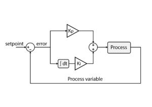
Once the different control loops have been properly identified, each state variable can be controlled separately. In this example, both control loops are proposed to be implemented using PI controllers.
The design of the current control loop is detailed in Basic PI control implementation (TN105).
For the design of the voltage control loop, different methods are used in the literature. Those methods are well detailed and explained in [1] and [2]. In this article, the Symmetrical Optimum (SO) will be used. The controller parameters are defined as:
$$\begin{array}{l}
T_{n2} = a^2 T_{d,eq} \\
T_{i2} = a^3 K_{d,eq} T_{d,eq}^2/T_2
\end{array}
\qquad\text{and}\qquad
\begin{array}{l}
K_{p2} = T_{n2} /T_{i2} \\
K_{i2} = 1 / T_{i2}
\end{array}$$
With \(T_{d,eq}\) the equivalent delay of the closed-loop current controller transfer function, defined as [2, 3]:
$$T_{d,eq} = 2 T_{d1} $$
The parameter \(T_d\) represents the sum of all the small delays in the system, such as the sampling delay or the modulation delay mentioned above. The product note PN142 explains how to determine the total delay of the system.
The parameter \(a\) is used to change the pole placement of the control function [2]. Low values give a small phase margin and high oscillations while increasing the value of \(a\) may lead to better damping, but a slower response. For the example provided in this technical note, this parameter is chosen as 4.
Academic references
[1] Karl J. Åström and Tore Hägglund; “Advanced PID Control”; 1995
[2] Chandra Bajracharya; “Control of VSC-HVDC for wind power”; NTNU; 2008
[3] R.S. Geetha, Ravishankar Deekshit and G. Lal; “Controllers For A VSC-HVDC Link Connected To A Weak AC System”; IOSR-JEEE; 2015
B-Box / B-Board implementation
ACG SDK implementation using Simulink
ACG SDK simplifies programming imperix controllers through automatic code generation. Control logic is implemented using standard Simulink blocks, and the ACG block set offers pre-built blocks for configuring the imperix controller’s I/O. The figure below illustrates this control implementation.

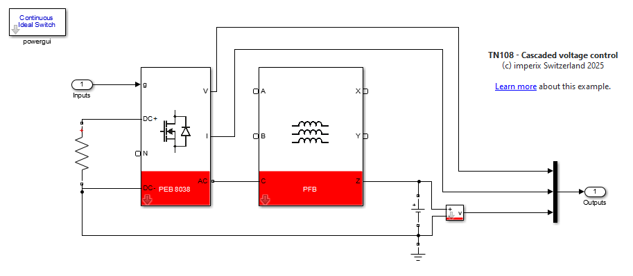
ACG SDK also enables offline simulation using Simulink/PLECS. By running the model in simulation mode, the control logic can be validated against a user-defined plant model. Furthermore, ACG SDK’s power library includes models of imperix power hardware, such as the PEB 8038 half-bridge module used in this example, built using the Simscape Electrical Toolbox from MathWorks. The figure below illustrates the implementation of the plant model.
Software resources
C/C++ code
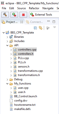
The imperix IDE provides numerous pre-written and pre-optimized functions. Controllers such as P, PI, PID and PR are already available and can be found in the controllers.h/.cpp files.
As for all controllers, PI controllers are based on:
- A pseudo-object
PIDcontroller, which contains pre-computed parameters as well as state variables. - A configuration function, meant to be called during
UserInit(), namedConfigPIDController(). - A run-time function, meant to be called during the user-level ISR, such as
UserInterrupt(), namedRunPIController().
The necessary parameters are documented within the controllers.h header file. They are namely:
KpandKi, proportional and integral gains, respectively.Tdthe derivative time-constant, which must be set to zero for a PI.limupandlimlow, the upper and lower saturation thresholds of the output.Ts, corresponding to the sampling (interrupt) period.N, the filtering factor of the derivative term, which is not used for a PI.
Implementation example
Results
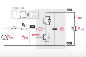
The cascaded voltage control has been tested with the boost converter example shown in PI-based DC current control (TN105).
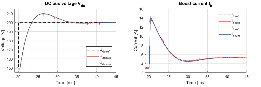
A step was performed on the DC bus voltage reference, in both simulation and experimental modes. The following graphs show a comparison between both results. An excellent agreement can be observed.
To go further
Beyond the example of a boost converter, the robust control architecture presented in this article can be used in many different DC-link-based converter topologies. This also applies to 3-phase converters such as the active front end (TN166) and more complex cascaded topologies including cascaded H-bridges (TN165) used in solid-state transformers (AN015) and medium-voltage STATCOMs (AN013).


