Table of Contents
This article aims to explore the Model Predictive Control (MPC) methodology in-depth, focusing on its operational principles, classification, and comparative analysis with conventional PID-based control. Furthermore, it attempts to enlighten the diverse applications and challenges associated with MPC implementation. Moreover, the article presents the Finite Control Set Model Predictive Control (FCS-MPC) method, a prominent variant of MPC.
What is Model Predictive Control?
The Model Predictive Control is an advanced model-based control method that relies on an accurate mathematical model of the controlled system to predict its future behavior. The MPC’s control strategy can be regarded as a constrained optimization problem, which consists of the discretized model of the plant and an objective function that can be tailored to the user’s control objectives. Starting from its current state, the behavior of the controlled system variables is predicted over a finite prediction horizon prediction, thus giving MPC the capability to anticipate system responses to disturbances and make informed decisions regarding optimal control outputs while considering system constraints and limitations. Rather than implementing the entire sequence of optimal control outputs computed during the optimization process, only the first element is executed, and this process is repeated at the next time step thanks to a receding horizon strategy.
MPC methods are often compared to traditional PID controllers. These two types of control nonetheless rely on different approaches and characteristics, which are discussed in the next Section.
Model Predictive Control vs classical PID control
MPC and PID-based control differ in many aspects, such as:
- Control strategy: By knowing the mathematical model of the controlled system, the MPC control strategy focuses on how the controlled variables will behave starting from the current information and the given prediction horizon. Conversely, PI control is a feedback-based control strategy that computes the control output based on the current error (the difference between the desired setpoint and the measured process variable) and its past behavior through proportional, integral and derivative terms [1].
- Robustness to disturbances: MPC, being a predictive control method, can find the best control action that minimizes the impact of disturbances over the given time horizon, leading to more stable control performance [2], [3]. Conversely, in the feedback-based control strategy of PID controllers, only the immediate control action is optimized, making PID controllers generally more susceptible to disturbances compared to MPC controllers.
- Constraint management: MPC naturally incorporates constraints on control inputs, state variables, and performance criteria into its optimization framework. It can enforce constraints on the system variables throughout the control process. Conversely, PID control does not directly handle constraint management. To ensure that system variables remain within their acceptable limits, one common approach is to incorporate limiters or saturation functions into the control loop to prevent the control output from exceeding the specified limits. However, unlike MPC, which proactively considers constraints during optimization, this approach in PID control is more reactive and therefore can be too aggressive in specific scenarios.
- Multivariable control: MPC streamlines the control process as it simultaneously controls multiple process variables and constraints, reducing the need for complex cascade configurations typically used in a linear control scheme. This is particularly useful in applications where compliance with limits is critical.
- Nonlinearities management: in MPC, nonlinearities in the system can be included in the model, avoiding linearizing the model for a given operating point and improving the operation of the system for all conditions [4]. This is advantageous because allows the controller to capture the system’s behavior across a wide range of operating conditions, enhancing the controller’s ability to maintain stable and optimal operation under varying conditions. When nonlinearities are present in the system, PID controllers may require additional tuning or the implementation of advanced techniques to mitigate their effects. However, unlike MPC, PID control does not inherently handle nonlinearities in the system model. Instead, engineers may need to employ techniques such as gain scheduling, adaptive control, or nonlinear control methods to address nonlinearities in the system dynamics.
The adaptability of MPC comes with a trade-off of increased implementation complexity. Unlike PID control, which is relatively straightforward to design and implement, MPC requires a more rigorous process that involves accurate modeling of the system dynamics and computationally intensive calculations. To implement MPC effectively, a precise mathematical model of the controlled process has to be developed, including dynamics and constraints. This modeling process can be complex and time-consuming, especially for systems with nonlinearities or time-varying behavior. Moreover, the optimization algorithms used in MPC require significant computational resources to solve the optimization problem in real-time. However, for systems where accuracy, robustness, and flexibility are critical, the benefits of MPC often outweigh the added complexity.
Classification of Model Predictive Control methods
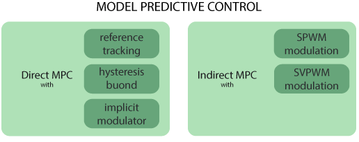
Model Predictive Control (MPC) includes a wide variety of methods with different approaches and applications. The authors in [5] propose a classification of these methods into two main groups, namely direct MPC methods and indirect MPC methods, depending on whether a modulator is used or not.
The following figure displays the main direct and indirect MPC methods.
Direct MPC
In direct MPC, control and modulation problems are formulated and solved in one stage, thus not requiring a modulator. The elements of the control output vector are the switching signals, a boolean vector, fed directly into the converter. Direct MPC methods can be further divided into:
- Direct model predictive control with reference tracking, also known as finite control set model predictive control (FCS-MPC), considers the discrete nature of power converters and their finite number of possible actuations to achieve the regulation of the controlled variables along their reference trajectories by directly manipulate the converter switches. An example of FCS-MPC using imperix tools is addressed in this article.
- Direct model predictive control with hysteresis bounds aims to maintain the system variable within desired bounds, optimizing control actions over a finite prediction horizon while considering constraints and control objectives. Thus, it provides smoother and more gradual control actions compared to the abrupt switching characteristic of a bang-bang controller, leading to improved system performance and stability.
- Direct model predictive control with an implicit modulator includes two strategies. The former includes methods that manipulate both switching signals and their application time to emulate PWM techniques and therefore presents variable switching time instants. This is done by computing both the optimal states and the associated duty cycles. The latter includes MPC methods combined with programmed PWM. The switching pattern and switching time instant are computed offline based on the chosen optimization criteria.
Indirect MPC
In indirect MPC, the controller computes the modulating signal/duty cycles, a real-valued vector, which is then fed into a modulator to generate the switching commands. Indirect MPC methods utilize sinusoidal PWM (SPWM) or space vector modulation (SVPWM). A detailed comparison of these modulators is addressed in SVPWM vs SPWM modulation techniques.
Regardless of whether the modulation stage is utilized, all MPC-based methods rely on the same fundamental principles outlined in the following Section.
Fundamental principles of MPC-based controllers
This section delves into the key elements of MPC-based controllers. Any deviation from these principles could worsen the performance or functionality of the MPC controller. Therefore, compliance with the following principles is essential for proper implementation.
Mathematical model of the plant
MPC is often based on continuous-time state-space models, which provide a comprehensive representation of the system dynamics. Conversely, discrete-time models are commonly used in digital control systems, where measurements and control actions occur at discrete intervals. Therefore, a discretization of the continuous-time state-space model is needed. To derive the state-space model:
- The variables that fully describe the model dynamics, which are typically related to the energy storage elements of the system, are chosen and aggregated into the state vector x.
- The manipulated variables are aggregated into the input vector, typically denoted by u. In direct MPC, these variables can indicate switch states, whereas in indirect MPC, they can represent the modulating signals.
- The output variables of the system are chosen and aggregated into the output vector, generally represented by y. These variables typically correspond to the measured variables, representing the system’s states that are directly observed or measured. They provide feedback to the controller, allowing it to adjust the control inputs to achieve desired system behavior indirectly.
As a result, the continuous-time state-space model takes this form:
$$\frac{dx\left(t\right)}{dt}=A_{}x\left(t\right)+Bu\left(t\right)$$
$$y\left(t\right)=C_{}x\left(t\right)$$
where \({\bf A}\), \({\bf B}\) and \({\bf C}\) are the system, input and output matrices, respectively. These matrices can be either time-invariant or time-variant.
Forward Euler, backward Euler and exact discretization are the most commonly employed discretization methods. The discretization is based on the first control design parameter, which is the sample time \(T_{s}\). The correct design of the sample time is crucial for stability since it determines how frequently the controller updates its control actions. If the sample time is too large, the controller may not respond quickly enough to changes in the system, leading to instability. Conversely, if the sample time is too small, it may introduce an unnecessary computational burden without significant improvement in control performance. Choosing an appropriate sample time balances the need for accurate control with computational efficiency.
Horizons
The correct choice of the horizons, namely the prediction horizon and control horizon, is important for achieving a balance between computational efficiency and control performance, ensuring accurate future behavior prediction and accurate control actions. Here is the main difference between the two:
- The prediction horizon is commonly used to refer to the time period over which the system’s future behavior is predicted and allows MPC to anticipate system responses to disturbances and make informed decisions about optimal control outputs. Therefore, the prediction horizon should be long enough to capture the dominant dynamic behavior of the plant. However, while a longer prediction horizon offers benefits in terms of disturbance rejection and long-term planning, it also comes with trade-offs in terms of computational complexity, response time, memory requirements, and sensitivity to model inaccuracies.
- The control horizon determines how far into the future the controller plans its actions, but it doesn’t directly refer to the prediction of the system’s behavior. The control horizon is defined as an integer value between 1 and the prediction horizon (included). An excessively small value leads to reduced degrees of freedom, while an excessively large value increases computation load and memory [5].
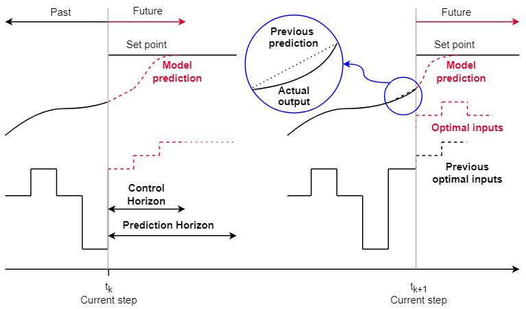
The controller operates at each sampling instant, denoted by ‘k’, to provide a control signal to the system. At each sampling instant, the future behavior is estimated by the model within the range of the prediction horizon. The estimated controlled variable response within the control horizon is determined by an output sequence calculated by the optimization algorithm. Subsequently, from this sequence, the one that satisfies the system constraints while minimizing the objective function is applied. As this control action is executed, the prediction horizon shifts, allowing the controller to reassess and adapt its predictions based on the updated system state. This iterative process continues at each sampling instant, utilizing the latest measurement information and recalculating the control sequences, thanks to the feedback introduced by the receding horizon.
For instance, let’s consider a solar power system with an energy storage system to store excess energy. In this scenario, the prediction horizon involves forecasting how much sunlight the solar power system is expected to receive over the next few hours, with a prediction horizon of 2 hours. With this foresight, a control algorithm can then determine how much energy should be stored in the batteries for the subsequent 30 minutes, constituting the control horizon. Therefore, the control horizon spans the timeframe during which battery storage management decisions are made based on the solar energy forecast. The receding horizon aspect implies that new information, such as weather changes, will be available after 30 minutes. This concept is illustrated in the following figure, where the new optimal inputs at the time step \(t_{k+1}\) are the decisions made by the control algorithm given the new information.
Objective function
The objective function guides the control algorithm to compute the optimal control action that best achieves the desired control objectives while considering system dynamics and constraints. The MPC-based controller’s performance is markedly related to the choice of the objective function and its parameters. The design of the objective function can include:
- Choice of a norm: a norm is a mathematical measure used to quantify the error between predicted and reference values. It helps to assess how closely the system’s behavior matches the desired trajectory or setpoint. Among all the possible norms, \(l_{1}\) norm and \(l_{2}\) norm are the most used. The former assigns a linear weight to errors, making the control system more robust to disturbances or measurement errors as it avoids significant penalties for outlier errors. The latter assigns a quadratic weight to errors, making the control system more sensitive to outlier errors. The main advantage is its tendency to produce smoother and more continuous solutions compared to the \(l_{1}\) norm. The authors in [7] show how the selection of different norms impacts closed-loop stability in FCS-MPC.
- Control effort penalization: the control effort penalization term, which is generally denoted as \(Δu\), is a term that can be included in the objective function to balance the trade-off between achieving the control objective and minimizing the control actions (i.e., effort) required to achieve it. The interpretation of the control effort differs depending on the type of MPC method. When direct MPC is concerned, penalization of the control signal increment often implies direct control of the switching frequency [8]. When indirect MPC is concerned, penalization of the control effort results in a less aggressive control with smoother control.
- Tuning of weighting factors: the objective function may consist of more than one term, giving rise to a multi-criterion optimization problem. Therefore, the weighting factor procedure, which is not trivial, prioritizes the different terms of the objective function. These values can be selected by exploring the trade-off curves or surfaces to find the Pareto optimal points [9], with trial-and-error methods [10], or with analytical expressions [11].
- Hard constraints: physical boundaries that must never be breached and can not be exceeded.
- Soft constraints: Soft constraints are added to the MPC objective function to allow for flexibility in constraint satisfaction. They are usually handled by introducing a slack variable, which represents the amount by which a constraint can be violated. An associated penalty term is then added to the objective function to penalize these violations, ensuring that the controller aims to minimize them while keeping the control problem feasible.
Once the user has established the desired control objectives, the objective function can be formulated accordingly. The future behavior of the system can be predicted over the prediction horizon based on \(U(k)\), where \(U\) is the sequence of manipulated variables that achieve the most desired system behavior, and the present state \(x(k)\). Then, the generic form of the objective function is [7]:
$$J\left(x\left(k\right),U\left(k\right)\right)=\sum_{i=k}^{k+N{p}-1}\left|\right|\Lambda\cdot y_{err}(i+1)||^{p}+\lambda_{u}||\Delta u(i)||{}^{p}+H_{c}+\rhoξ_{i}$$
where:
- \(N_{p}\) is the prediction horizon.
- \(||\cdot||^{p}\) is the \(l_{p}\) norm.
- \(\Lambda\) is a diagonal matrix representing the weighted \(p\)-norm. It is used in cases where there are multiple outputs and prioritization among them is necessary [12].
- \(y_{err}\) is the output reference tracking term, which quantifies the deviation of the system’s predicted output from the desired reference trajectory or setpoint over the prediction horizon.
- \(Δu(i)\) is the control effort penalization term.
- \(λ_{u}\) is the weighting factor for the control effort penalization term.
- \(H_{c}\) is the hard constraint term.
- \(ξ_{i}\) is the slack variable and \(\rho\) the associated penalty weight.
In the finite control set model predictive control example, the generic objective function takes this form:
$$J=\left|\right|y_{err}\left(i+2\right)\left|\right|^2=\left(i_{i\alpha,i+2}^{\star}-i_{i\alpha,i+2}^{}\right)^2+\left(i_{i\beta,i+2}^{\star}-i_{i\beta,i+2}^{}\right)^2$$
The objective function uses a l2–norm with a reference tracking term for the inverter current, which is computed in the stationary (αβ) reference frame, with no weighting factors or penalization terms.
An example of a hard constraint associated with this example to limit the converter current to \(I_{max}\) could be:
$$H_{c}=\left\lbrace\begin{array}{l}inf,\left|\right|i_{i,k+2}\left|\right|\ge I_{\max}\\ 0,_{}otherwise\end{array}\right.$$
This term activates when the magnitude of the inverter current exceeds the limit \(I_{max}\), thus favoring control actions that force the current down to normal values.
Finite Control Set Model Predictive Control stands out in scientific literature as one of the most widely studied and discussed MPC techniques. Its popularity stems from its intuitive design process and implementation, making it a favored choice for researchers and practitioners alike. Then, given the importance of this method, a brief description of FCS-MPC’s main characteristics is given in the following Section.
Characteristics of Finite Control Set Model Predictive Control
Finite Control Set Model Predictive Control considers the discrete nature of power converters, which operate with a finite number of possible switching states. This approach employs reference tracking techniques to regulate system variables along predetermined trajectories by directly manipulating the switching states. The main characteristics of FCS-MPC can be listed as:
- No modulator: FCS-MPC is categorized as a direct MPC method, eliminating the need for a modulator to generate control signals.
- Variable switching frequency: the absence of a modulator results in a variable switching frequency, offering flexibility to adapt to varying sampling or control frequencies based on system conditions or design preferences.
- Online optimization: in FCS-MPC, online optimization allows the controller to adapt its control strategy in real-time based on new data, ensuring optimal performance for dynamic applications. On the other hand, explicit MPC computes the control law offline and directly applies it online without further optimization, resulting in faster execution but potentially reduced adaptability to dynamic changes compared to traditional MPC methods.
- Low complexity: FCS-MPC can also use a one-step prediction horizon, thus reducing the computational complexity of the controller. This is useful when a fast control is required, as it eliminates the need for computationally intensive calculations. For instance, in a three-phase two-level inverter the possible combinations of control actions that the MPC algorithm considers when optimizing the control strategy are \(2^{3N_{p}}\), where \(N_{p}\) is the number of steps of the prediction horizon. The number of possible solutions increases exponentially with the length of the prediction horizon, which can lead to computational challenges in searching for the optimal control sequence.
- Handling Constraints and Nonlinearities: FCS-MPC can incorporate constraints and nonlinearities into the control optimization process. This flexibility allows the controller to enforce safety limits and meet performance requirements effectively.
To go further
An applicative example of the finite control set MPC method is addressed in this article.
References
[1] L. Dai, Y. Xia, M. Fu, and M. S. Magdi, “Discrete-Time Model Predictive Control”, in Intechopen, Dec. 2012.
[2] S. Bhowmik, P. K. Gayen and A. Mitra, “Performance Comparison between PI based Control and Model Predictive Control of Voltage Source Inverter under Load Variations,” in IEEE EDKCON, Kolkata, 2022.
[3] A. A. Zaki Diab, D. A. Kotin, V. N. Anosov and V. V. Pankratov, “A comparative study of speed control based on MPC and PI-controller for Indirect Field oriented control of induction motor drive,” in 12th International Conference on Actual Problems of Electronics Instrument Engineering, Novosibirsk, 2014.
[4] J. Rodríguez and P. Cortés, Predictive Control of Power Converters and Electrical Drives, New York, Wiley, 2012.
[5] P. Karamanakos, E. Liegmann, T. Geyer and R. Kennel, “Model Predictive Control of Power Electronic Systems: Methods, Results, and Challenges,” in IEEE Open Journal of Industry Applications, Aug. 2020.
[6] P. Cortes, M. P. Kazmierkowski, R. M. Kennel, D. E. Quevedo and J. Rodriguez, “Predictive Control in Power Electronics and Drives,” in IEEE Trans. on Industrial Electronics, Dec. 2008.
[7] P. Karamanakos, T. Geyer and R. Kennel, “On the Choice of Norm in Finite Control Set Model Predictive Control,” in IEEE Trans. on Power Electronics, Aug. 2018.
[8] T. Geyer, Model Predictive Control High Power Converters and Industrial Drives, New York, Wiley, 2016.
[9] S. Boyd and L. Vandenberghe, Convex Optimization, Cambridge Univ. Press, Cambridge, 2004.
[10] P. Cortes et al., “Guidelines for weighting factors design in Model Predictive Control of power converters and drives,” in IEEE Trans. of Power Electronics, May 2009.
[11] T. Geyer, “Algebraic Tuning Guidelines for Model Predictive Torque and Flux Control,” in IEEE Trans. on Industry App., Oct. 2018.
[12] M. A. Perez, J. Rodriguez, E. J. Fuentes and F. Kammerer, “Predictive Control of AC–AC Modular Multilevel Converters,” in IEEE Trans. on Industrial Electronics, July 2012.


