Table of Contents
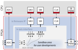
This technical note shows how to build a decoder IP for a Delta-Sigma Modulator and establish communication with such a device through USR ports of the B-Box RCP and B-Board PRO. The corresponding approach uses the user-programmable area inside the FPGA, also known as sandbox.
Introduction
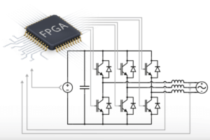
Delta-Sigma Modulators are a class of analog-to-digital converters (ADCs) that produce a high-frequency data stream (1-bit), whose pulse density represents the acquired analog value. In data acquisition applications, such devices are particularly useful when only a few (typ. 1-2) digital lines are available. This may notably be essential when data must be carried across a galvanic isolation barrier, such as in numerous power electronic applications.
Delta-sigma modulation may represent various modulation techniques, resulting in different types of data encoding methods for the digital stream. Common types are Non-Return-to-Zero (NRZ) and Manchester coding. These techniques differ in their bitrates, but may also offer (or not) the possibility of recovering the clock from the bit stream.
Clock recovery is often an essential feature. Indeed, by recovering the data clock directly from the stream itself, a separate clock becomes dispensable, which further reduces the number of required communication lines. In practice, a delta-sigma modulator can communicate with its associated demodulator with only one digital line!
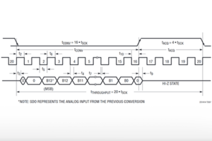
This note provides an implementation example centered around the AMC1035 delta-sigma modulator, which supports two output encoding methods: Non-Return-to-Zero (NRZ) and Manchester coding. The data rate of NRZ coding is 9~21MHz while the data rate of Manchester coding is 9~11MHz. In the next chapter, a decoder for each coding method will be provided.
Related notes
- Instructions on how to build an FPGA project template and how to exchange data between the CPU and the sandbox using the AXI4-Stream interface module can be found in Getting started with FPGA control development.
- The page AXI4-Stream IP from Xilinx presents the AXI4-Stream interface and the Xilinx AXI4-Stream IPs.
- Another example of how to expand the number of ADC inputs using SPI and user ports is available in FPGA-based SPI communication IP for ADC.
Software sources
Delta-sigma decoder implementation
Synchronous decoder for NRZ encoding
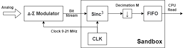
In synchronous mode, the clock signal is generated by the FPGA, transmitted to the delta-sigma modulator, and used by the latter for the modulation. The same clock is then used for decoding the NRZ bit stream that is received by the FPGA. This approach uses two physical USR ports available from the sandbox and one three-order sinc filter as a decimator.
In general, the suggested system diagram for a synchronous decoder is shown below.
The VHDL codes are given below.
- The AMC1035 sends a NRZ (Non-Return-to-Zero) coded bit stream
- The clock is generated by the FPGA and fed to the AMC1035 and decoder block, synchronously
- The decimation ratio M can be configured from the CPU using an SBO register
- The output data is a 32-bit unsigned integer available on an AXI4-Stream interface
The sinc3 filter is implemented using CIC (Cascaded integrator–comb filter) architecture as shown below. CIC is an efficient implementation of a moving-average filter, which is built using adders and registers only. The relationship between the decimation ratio M and the output data width is given in the table below.
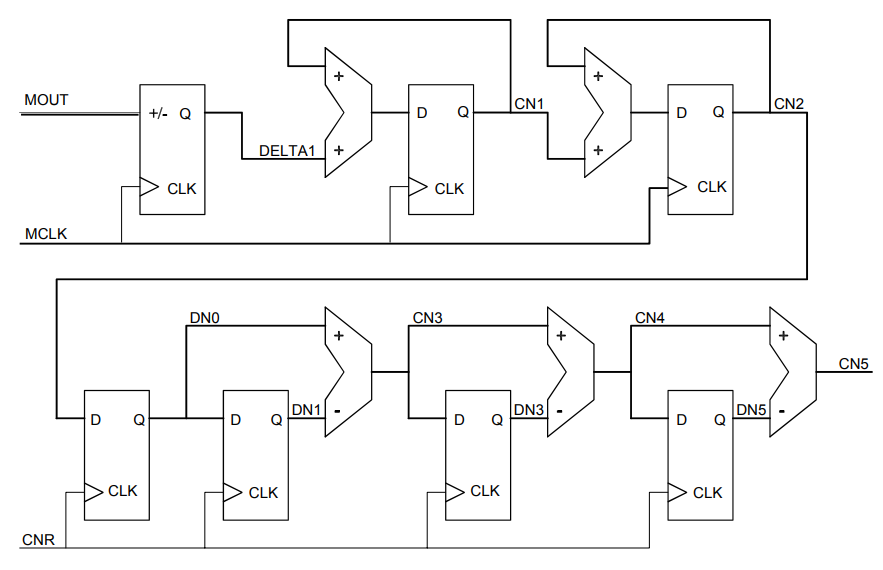
| Decimation | Date Rate (kHz) | GainDC (bits) | Total Output Width (bits) |
| 4 | 2500 | 6 | 7 |
| 8 | 1250 | 9 | 10 |
| 16 | 625 | 12 | 13 |
| 32 | 312.5 | 15 | 16 |
| 64 | 156.2 | 18 | 19 |
Manchester decoder
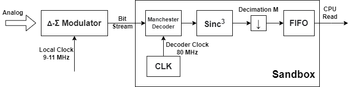
In Manchester coding mode, the AMC1035 can be clocked with a local clock, whose phase and frequency are unknown. On the FPGA side, this approach needs only one user port, for receiving the data stream, and one three-order sinc filter as decimator. In addition, a Manchester decoder is needed to translate Manchester-encoded data to NRZ. This mode has the advantage of reducing the number of used user ports but the drawback of a reduced data rate (down to 9~11MHz).
In general, the suggested system diagram using the Manchester decoder is shown below.
The VHDL codes are given below.
- The AMC1035 works in the Manchester coding mode
- The clock used by the Manchester decoder can be asynchronous to the input data, but must be between 5 and 12 times, nominally 8 times, faster than the input data rate. For the AMC1035 we can simply use a 80MHz clock
- The decimation ratio M can be configured by the CPU using an SBO register
- The output data is a 32-bit unsigned integer using AXI4-Stream interface
This FPGA implementation of a Manchester decoder uses two registers and a XOR gate for transition detect, and one divide-by-six Johnson counter that locks up in the 000 state. Once a transition is detected, the STROBE flag will be asserted, indicating valid data, then the 6-counter will terminate STROBE for the following 5 periods. This procedure ensures that no between-bit transition is detected by mistake.
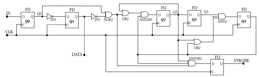
The implementation of sinc3 filter uses the previously introduced CIC architecture. However, due to the different data-valid mechanism, the sinc3 filter only accepts input data when STROBE is asserted, whereas in the previous design, it accepts data at each rising edge of the synchronous clock.
CLK for the clock input. They shall however NOT be confused.For the synchronous decoder block, the
CLK is the clock used by the AMC1035 running at 9~21MHz.For the Manchester decoder block, the CLK is a specialized clock for Manchester decoding, running at 80MHz.
The reason why the same name is used for both clocks is that the AXI4-Stream interface is used to simplify the connection between blocks. And any clock used by the AXI4-Stream must be named according to Xilinx conventions. Otherwise, a clock cannot be automatically recognized.
Delta-sigma modulator testbench
For each block, a VHDL testbench simulating NRZ/Manchester coded bit streams is provided to validate the behavior of the two decoders.
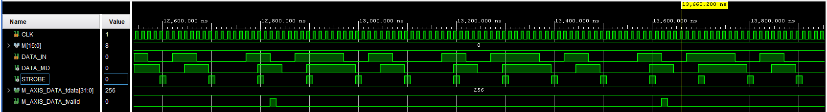
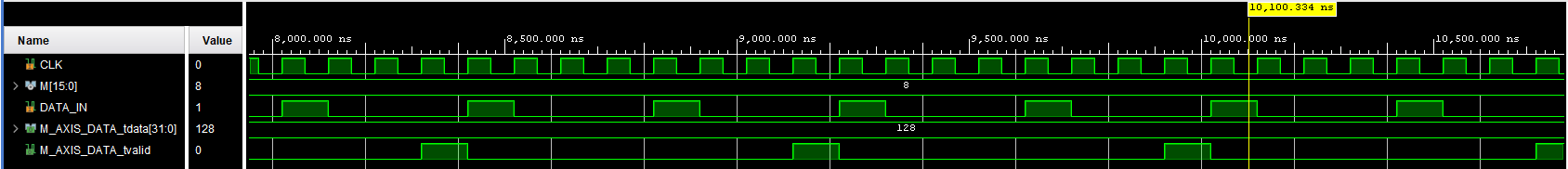
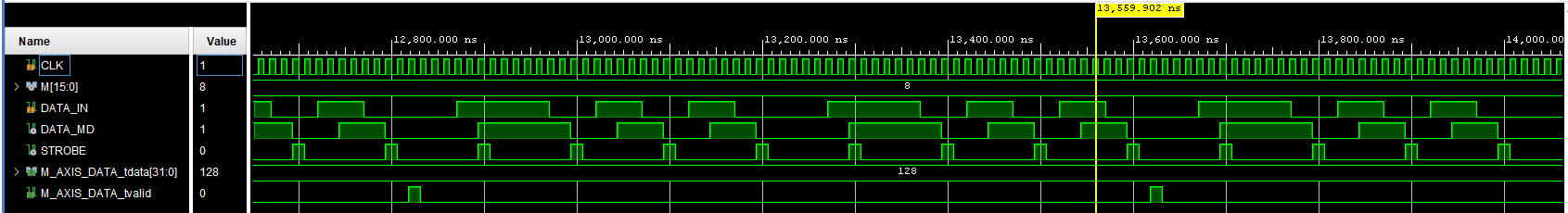
In this testbench, we chose a decimation rate of \(M = 8 \). The output word size is then 9 bits, and the maximum output range is \(2^9-1 = 511\). We can select different input patterns, and the sinc3 filter output will be proportional to the number of ‘1’s in the bit stream.
Input pattern = “1001” (50% 1s), output = 256
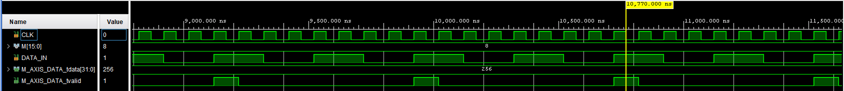
Input pattern = “1000” (25% 1s), output = 128
Deployment on the B-Board PRO
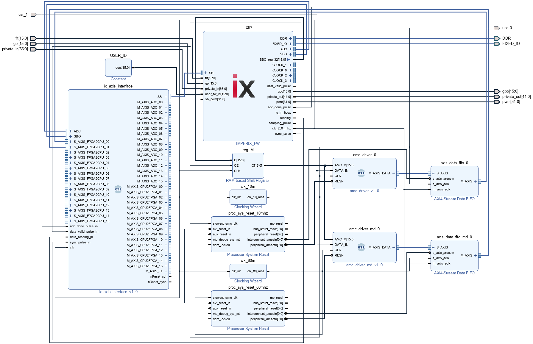
This Vivado project shows how to add the synchronous decoder and/or Manchester decoder block to the B-Board firmware and send output data to the CPU through ix_axis_interface. This project starts from the template introduced in Getting started with FPGA control development, and the following blocks are added to the project.
clk_10mis the 10MHz clock source for the AMC1035 and its output is connected to the physical pinUSR[0]clk_80mis the 80MHz clock for Manchester decodingamc_driver_0andamc_driver_md_0are the synchronous decoder and Manchester decoder blocks, their input DATA_IN is connected to the physical pinUSR[1]- Two AXI4-Stream FIFOs are used to deal with the asynchronous data transfer between different clock fields, their outputs are sent to the CPU through
FPGA2CPU_00andFPGA2CPU_01 - The decimation ratio M is sent to the FPGA through
SBO_reg_32 proc_sys_reset_10mhzandproc_sys_reset_80mhzprovide active low resets for the 10MHz and 80MHz clock fields, theirext_reset_ninput is connected tonReset_syncport ofix_axis_interface
Before synthesizing the project, Vivado will report timing failure at reg_M because the asynchronous data transfer (due to the 250MHz FPGA main clock and the 10MHz/80MHz decoder clock) may lead to a metastable state. However, since we know that, in reality, there will be enough time to wait for a new stable state, this issue can be safely ignored by setting a longer maximum delay. In order to do this, a new constraint file must be added to the Vivado project following the instructions in Getting started with FPGA control development. The constraints below shall be sufficient to circumvent this issue.
set_max_delay -from [get_pins {top_i/reg_M/U0/i_synth/i_bb_inst/gen_output_regs.output_regs/i_no_async_controls.output_reg[*]/C}] -to [get_pins {top_i/amc_driver_0/U0/P_CNR.CNR_cnt_reg[*]/R}] 4.0
set_max_delay -from [get_pins {top_i/reg_M/U0/i_synth/i_bb_inst/gen_output_regs.output_regs/i_no_async_controls.output_reg[*]/C}] -to [get_pins top_i/amc_driver_0/U0/CNR_reg/D] 4.0
set_max_delay -from [get_pins {top_i/reg_M/U0/i_synth/i_bb_inst/gen_output_regs.output_regs/i_no_async_controls.output_reg[*]/C}] -to [get_pins {top_i/amc_driver_md_0/U0/CNR_cnt_reg[*]/D}] 4.0
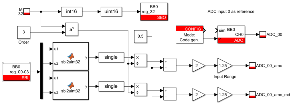
set_max_delay -from [get_pins {top_i/reg_M/U0/i_synth/i_bb_inst/gen_output_regs.output_regs/i_no_async_controls.output_reg[*]/C}] -to [get_pins top_i/amc_driver_md_0/U0/CNR_rising_edge_reg/D] 4.0On the CPU side, a Simulink file is provided, which reads the sinc3 filter output and converts the uint32 data to Volts. As introduced in its datasheet, the full-scale input range of AMC1035 is +/-1.25 V, then the sinc3 filter with decimation ratio \(M \) converts the input to \(1+3\log_{2}{M} \) bits. Based on this, data can be recovered using the program below.
Experimental results
The following hardware was used:
- B-Board evaluation kit
- AMC1035 evaluation module
- Function generator
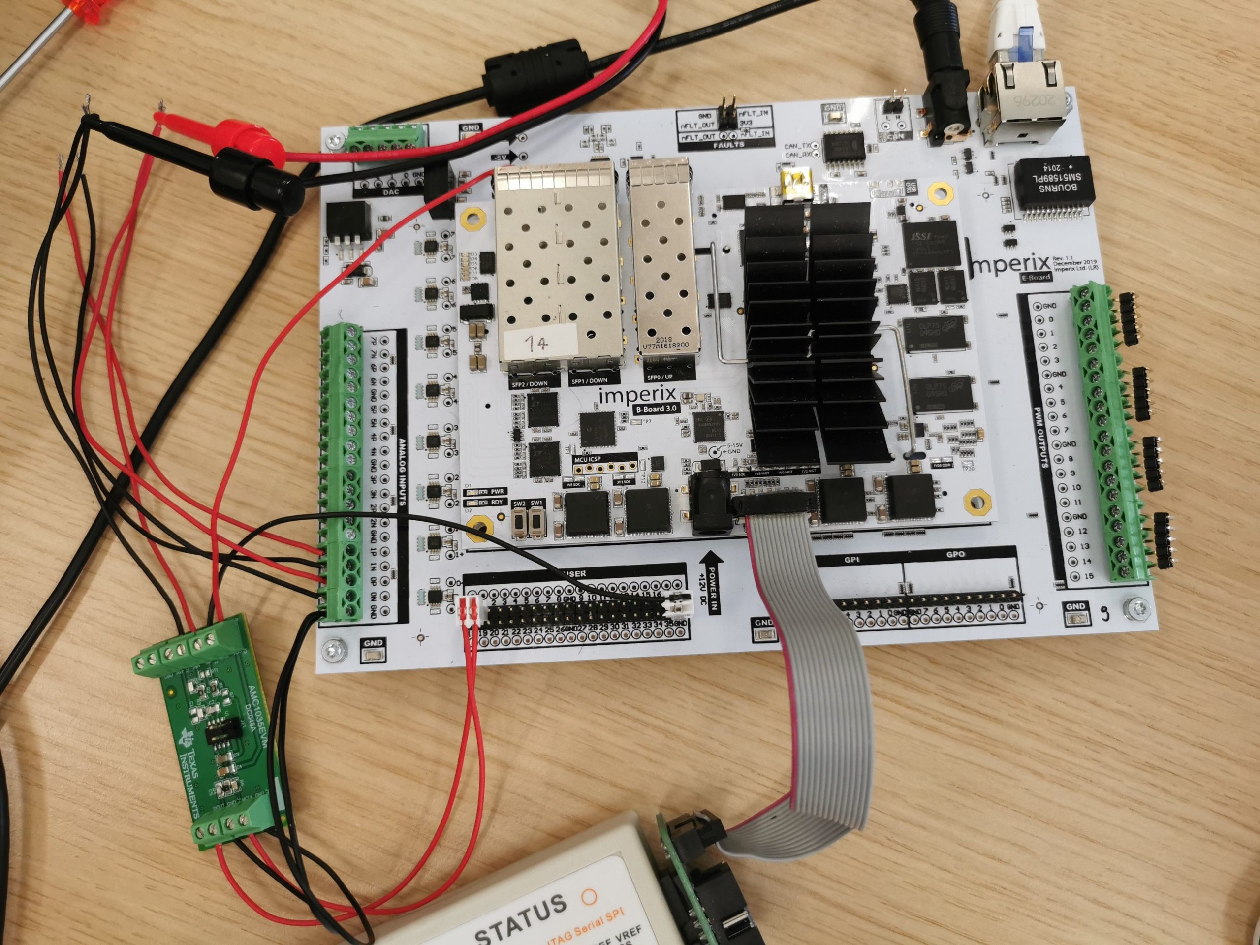
A 50Hz 2V (p-p voltage) sine wave is connected to ADC 0 of the B-Board and the input port of the AMC1035, and the results are plotted in BB Control. The three signals overlap properly, showing that the synchronous decoder and Manchester decoder blocks for the delta-sigma modulator both work properly.