Table of Contents
This page presents an implementation example of Selective Harmonic Elimination (SHE) using the PP-PWM modulator. This example addresses a high-power 3-level NPC inverter tied to an induction machine, both implemented using Hardware-In-the-Loop simulation.
The harmonic performance of Programmed Pattern PWM with SHE is compared to the conventional carrier-based approach by analyzing the Total Harmonic Distortion (THD) and Weighted Total Harmonic Distortion (WTHD). The control algorithm is developed using the ACG SDK and is executed on the B-Box RCP digital controller, which is then connected to an RT-Box simulator from Plexim.
What is Selective Harmonic Elimination?
The main idea behind Selective Harmonic Elimination is to minimize – or even eliminate – specific harmonics from the current spectrum produced by a converter. To do so, the switching angles are pre-computed and pre-optimized, generally off-line. In most cases, the corresponding optimization process not only minimizes the targeted harmonics but also tends to minimize the overall amount of harmonics, that is THD.
SHE corresponds to one possible family of objectives that aim at shaping the switching harmonics. Other modulation techniques implementing Optimized Pulse Patterns (OPPs) exist, for instance targeting the total harmonic distortion or weighted total harmonic distortion.
For the optimization process itself, the higher the pulse ratio (i.e number of switching angles per period), the higher the number of degrees of freedom. For instance, using the assumption of quarter-wave symmetry (which simplifies greatly the SHE problem), the number of harmonics that can be eliminated corresponds to the number of angles per quarter-wave [2].
Most optimization algorithms cannot be performed in real-time. They indeed usually require solving a nonlinear optimization problem [3] that is time- and resource-consuming. Therefore, the sets of optimized angles, each corresponding to a specific modulation depth, are often pre-computed, stored in a look-up table (LUT), and retrieved during the real-time operation. More information on how to compute optimized pulses patterns for the PP-PWM peripheral is given in PP-PWM – Programmed Patterns PWM.
Minimizing the current harmonic distortion will have the benefit of relaxing the filtering requirements, which can be useful, especially for high-power converters that characterize with a low relative switching frequency (pulse number) [1]. Selective Harmonic Elimination with programmed pattern modulation is hence attractive for applications such as high-power motor drives (for crushers, pipeline networks, hydro storage pumps, …), active rectifiers, or grid-connected converters (like STATCOMS for instance) [1].
Modulation with programmed patterns
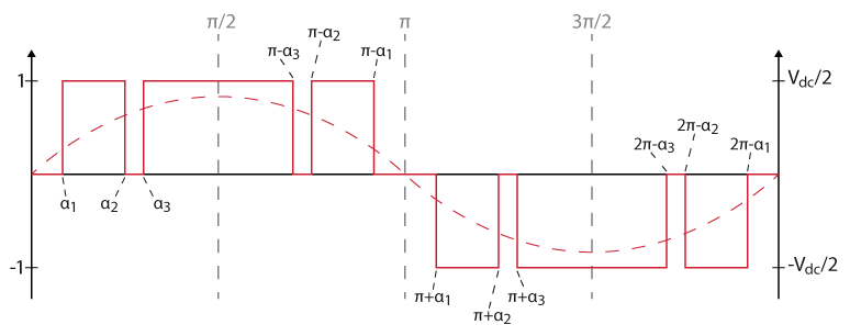
As aforementioned, the FPGA-based PP-PWM peripheral is here used to implement Pulse Width Modulation with Selective Harmonic Elimination. An overview of a switching signal generated by the modulator, configured with three angles per quarter period, is illustrated below:
As previously mentioned, the sets of switching angles are stored in a look-up table (LUT) for the real-time operation of the converter and each set of angles corresponds to a modulation depth. The modulation index m, computed by the control algorithm, will then select the appropriate set of switching angles from the LUT to be sent to the PP-PWM block. This is illustrated by the block diagram below.
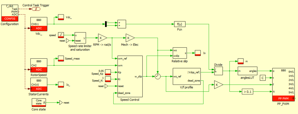
Furthermore, since a set of angles corresponds to a modulation depth, the corresponding resolution is defined by the number of sets stored in the LUT. Usually, in-between 10 and 100 sets of switching angles are computed to keep the size of the LUT reasonable. Additionally, if needed, the angles can be linearly interpolated in real-time [1]. This is shown below.
References
[1] M. S. A. Dahidah, G. Konstantinou and V. G. Agelidis, “A Review of Multilevel Selective Harmonic Elimination PWM: Formulations, Solving Algorithms, Implementation and Applications,” in IEEE Transactions on Power Electronics, Aug. 2015, DOI: 10.1109/TPEL.2014.2355226. IEEE Xplore.
[2] H. S. Patel and R. G. Hoft, “Generalized Techniques of Harmonic Elimination and Voltage Control in Thyristor Inverters: Part I–Harmonic Elimination,” in IEEE Transactions on Industry Applications, May 1973, DOI: 10.1109/TIA.1973.349908. IEEE Xplore.
[3] A. Birth, T. Geyer, H. d. T. Mouton and M. Dorfling, “Generalized Three-Level Optimal Pulse Patterns With Lower Harmonic Distortion,” in IEEE Transactions on Power Electronics, June 2020, DOI: 10.1109/TPEL.2019.2953819. IEEE Xplore.
[4] J. Meili, S. Ponnaluri, L. Serpa, P. K. Steimer and J. W. Kolar, “Optimized Pulse Patterns for the 5-Level ANPC Converter for High-Speed High Power Applications,” IECON 2006, 2006, DOI: 10.1109/IECON.2006.347555. IEEE Xplore.
Experimental results
To validate the SHE implementation, the performance of a conventional carrier-based modulation is compared to the programmed pattern modulation method. For that, the harmonic distortion of a 3-level NPC inverter is analyzed. This application was chosen since it would typically benefit from Selective Harmonic Elimination. Indeed, the conditions with low switching frequency and low pulse number are where the programmed pattern modulator with Selective Harmonic Elimination is expected to provide the most benefits [4].
In the presented example, the pulse number is selected to be 12, corresponding to 3 switching events per quarter wave. The switching angles are optimized in order to reduce/eliminate the 5th, 7th, and 11th harmonics, using the quarter-wave symmetry assumption.
The carrier-based and SHE control models and the simulated HIL plants can be downloaded from the link below. More information related to the HIL implementation is provided in TN178.
V/f control
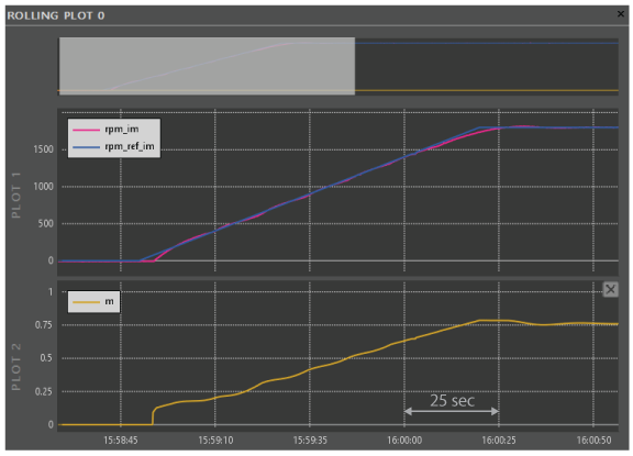
The induction machine is controlled using a simple V/f algorithm, detailed in TN138: V/f control of an induction machine. The figure below shows the speed tracking performance and the corresponding modulation index acquired with Cockpit.
Spectral analysis
The following plots show the stator currents for both modulation techniques when the machine is spinning at 1800rpm and an apparent switching frequency is set at 360Hz (i.e. 12 pulses period). The switching frequency being fairly slow (due to the size of the converter), the currents exhibit significant ripple.
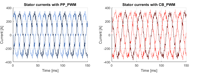
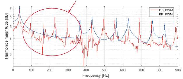
The harmonic components of the stator currents are shown in the figure below. As it can be observed, the modulation with Selective Harmonic Elimination does manage to dampen the first harmonics in the signal. The magnitudes of the first harmonics are clearly lower with the SHE modulation approach.
Finally, in order to quantitatively analyze the harmonic content, the Fourier transform is then computed so that frequency bins are exact multiples of the fundamental (30Hz in this case). The THD and WTHD can then be computed. The results are shown in the table below.
| PP-PWM with SHE | CB-PWM | |
|---|---|---|
| THD [%] | 20.6 | 23.4 |
| WTHD [%] | 11.5 | 14.2 |
When comparing SHE-PWM with CB-PWM, the THD and WTHD show the superior performance of the SHE-PWM. Note that minimizing the overall THD or WTHD was not the criterion used for the computation of the switching angles. Only minimizing the 5th, 7th and 11th harmonics is targeted. Nevertheless, removing the first harmonics does improve the harmonic performance of the signal, especially when considering the WTHD.


