Table of Contents
This technical note offers insights into the SS-PWM peripheral block, which is part of the standard firmware of imperix controllers. The SS-PWM block provides multilevel Pulse Width Modulation (PWM) as well as an integrated submodule balancing mechanism derived from the Sort-&-Select approach initially proposed in [1].
Background and motivations
The generation of modulated multilevel waveforms is a long-established topic for multilevel converters. Historically, cascaded converters mostly used modulation techniques that rely on multiple carriers. The latter are then carefully arranged (e.g. phase-shifted) so that the resulting waveform features multiple voltage steps as well as an increased apparent switching frequency [1].
In this first case, the balancing of the submodule voltages is a separate concern, entirely distinct from the modulation, which is addressed using dedicated control loops (e.g. local voltage control loops). This approach has been used since the late ’90 for cascaded converters with separate DC sources [2]. It was first applied to Modular Multilevel Converters as well in 2008 [3].
Independently from these conventional approaches, Modular Multilevel Converters were immediately proposed with a special modulation and balancing approach, which dynamically attributes the switching actions to suitable submodules, as a function of their relative capacitor voltage and power flow direction [4].
The elegance of the Sort-&-Select PWM technique lies in its simplicity and hence robustness. For balancing, only the relative ranking and the arm current polarity are required. The strategy can be hence easily applied to various converter topologies and modulation techniques (conventional PWM, nearest level modulation, selective harmonic elimination, etc.).
Sort-&-select balancing and PWM for MMC
One of the challenges associated with MMCs is to balance the capacitor voltages among all submodules. Adequate balancing ensures that the total blocking voltage is equally spread among submodules so that individual ratings are not exceeded. To some extent, submodule voltages balancing also contributes to the quality of the output voltage waveform. The overall balancing problem can generally be split into three distinct sub-problems:
- Submodule-level balancing, namely between submodules of the same arm.
- Converter-level balancing, namely balancing between the different arms.
- Overall energy control.
The Sort-&-Select modulation deals exclusively with submodule-level balancing. As such, the converter-level balancing and overall energy control are left as further control problems. The latter fall outside the scope of this note and are addressed in dedicated articles.
Algorithm of the imperix SS-PWM for MMC
Operating principles
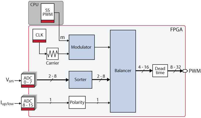
This section details the operation of the SS-PWM hardware as implemented within imperix controllers. The diagram below introduces the main blocks and gives an overview of the FPGA implementation. Documentation regarding how to use the SS-PWM blocks is given in SS-PWM – Multilevel PWM with Sort-&-Select balancing.
The FPGA-based SS-PWM for MMC essentially contains three subsystems:
- The Modulator is responsible for generating/synthesizing the multilevel waveform. Its output is the exact desired waveform, defined with a very small sampling period (here 4ns).
- The Sorter is aimed at ranking the submodules as a function of their charge level (capacitor voltage). Its output is a list of indices.
- The Balancer is tasked to identify the level transitions within the desired multilevel waveform and to dynamically assign the corresponding switching events to suitable submodules.
Modulator
The input of the modulator is the modulation index m. Its range is [0;N] for operation half-bridge submodules, respectively [-N;N] for operation with full-bridge submodules. N is the number of usable submodules par arm.
Based on the real-valued index m, the modulator generates the discrete value requested_lvl, which is modulated with the configured carrier signal. This defines, at every instant, how many modules are inserted (and apply their voltage) to the arm.
As shown in the diagram below, the output waveform is in fact the sum of two parts:
- The lower integer part of
mrepresent modules that are inserted all along a given switching period. - The fractional part of
mis equivalent to a duty-cycle that is applied to an additional module, only inserted during part of the switching period.
This way, the average number of modules inserted during a given switching period is equal to the modulation index m. Interestingly, this approach is also compatible with staircase modulation, provided that m is an integer staircase waveform by itself.
Sorter
The sorter has direct access to the digitally-converted values of the capacitor voltages. By sorting their values from the highest to the lowest, the sorter is able to generate a list of submodule indices, ranked in descending order.
When a large number of submodules must be compared and sorted, the algorithmic complexity of the sorting algorithm may become a challenge. In this case, it may be sufficient to only identify the (few) most, respectively least charged submodules. However, as the number of available I/Os on imperix controllers is limiting the number of submodules to N≤ 8 per arm anyway, the implemented sorting algorithm is a full sort (namely a simple even and odd sorting algorithm).
Balancer
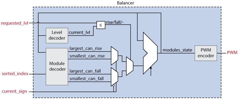
The balancer is responsible for identifying the submodule to be switched (i.e. inserted or bypassed) as a function of the sorting results, arm current polarity, and current switching states. This process has multiple steps:
First, four candidate submodules are identified:
– The least charged module that can be inserted, ie. accept a voltage rising switching event smallest_can_rise
– The least charged one that can be bypassed, i.e. accept a voltage falling event smallest_can_fall
– The most charged one that can be inserted largest_can_rise
– The most charged one that can be bypassed largest_can_fall.
Second, according to the arm current polarity current_sign, only one submodule is selected for each type of switching transition (voltage rising or falling event).
In parallel, the current module states are decoded to identify the current level, i.e. the number of submodules that are currently inserted inside the arm. For half-bridge submodules, current_lvl is comprised within the range [0;N], respectively [-N;N] for operation with full-bridge submodules.
In parallel also, by comparing the instantaneous values of current_lvl and requested_lvl, the subsequent sampling period can be flagged with a transition type: rise if the requested level is higher, respectively fall if the requested level is lower. In case current_lvl and requested_lvl are equal, the transition type is – (none).
Third, based on the detected transition type, only one submodule is eventually selected among the two that were previously identified during the second step. This final candidate submodule is the only one that will see its state modified during the sampling period.
Finally, after defining the new state for the selected submodule, the PWM encoder defines the gate-driving signals for each power semiconductor using a basic truth table following table. When transitions occur, a configurable dead-time is introduced between complementary signals.
A few remarks are worth noting regarding the operation of the Balancer:
- Since only one submodule is switched at once, it is guaranteed that there are no “effectiveless” switching events, i.e. switching actions that result in no direct change of the arm voltage.
- This principle also guarantees that the ratio between the average switching frequency seen by each submodule and the apparent switching frequency is optimum.
- Due to this also, in case the
current_lvlandrequested_lvldiffer by more than one level (such as in case of a very fast transient) only one change of the output level can be achieved per sampling period (4ns). Therefore, switching from the level -8 to +8 would require 48ns, which remains almost instantaneous for most applications.
Open-loop operation of SS-PWM for MMC
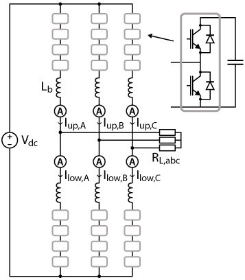
As an exemplary use case, Sort-&-Select modulation is applied to a Modular Multilevel Converter connected to a passive three-phase load. No converter-level balancing or energy control is performed, which also means that the so-called circulating currents are not shaped in a specific manner. Overall, this system is therefore controlled in a purely open-loop manner in the sense that there are no P, PI, or PID controllers regulating quantities explicitly.
Software resources
The provided Simulink files contain the control algorithm and a model of the plant, allowing for both simulation and automated code generation for this scenario.
Hardware and sofware configuration
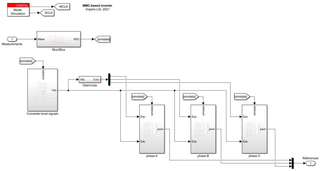
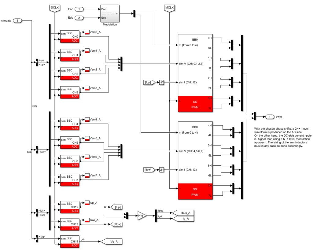
The control model is organized using three main blocks, one for each phase-leg, which contain all the ADC and PWM configurations. In addition, the control model includes a basic “open-loop” waveform generation block that produces the requested AC voltages as a function of the available DC bus voltage.
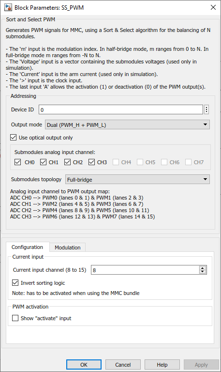
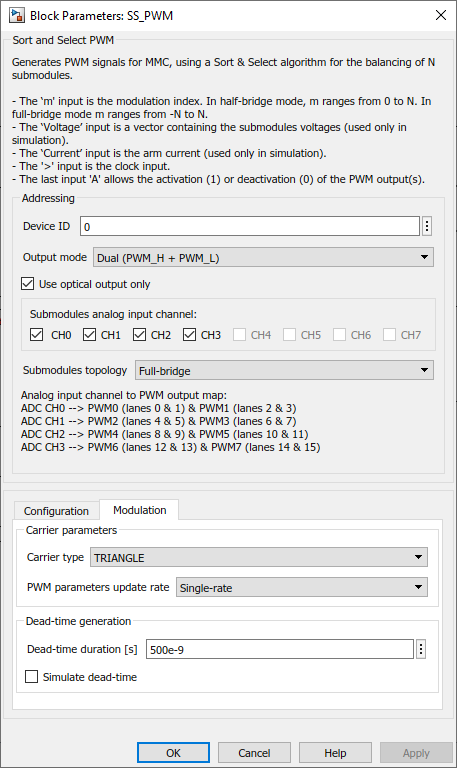
As seen above, one SS-PWM block is used for each MMC arm (meaning two blocks per phase-leg). They are configured as shown below:
The Submodules analog input channel corresponds to the analog inputs and PWM outputs to which the submodules are connected. The block is configured to work with half-bridge modules and the invert sorting logic parameter is enabled since the modules used are PEH2015 (for further details on the configuration, please refer to the software documentation: SS-PWM).
Also, note that the inverted carrier is configured in all the modulators driving the lower arms. This way, a 2N+1 waveform is produced on the AC side which results in less filtering required, with the downside of having larger current ripples on the DC side.
Experimental results
The typical performance of the SS-PWM for MMC peripheral block is shown below.
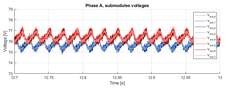
It is however clear that the submodules belonging to the upper and lower arms are not well balanced together. Elementary techniques for converter-level balancing are introduced on the Three-phase MMC converter page.
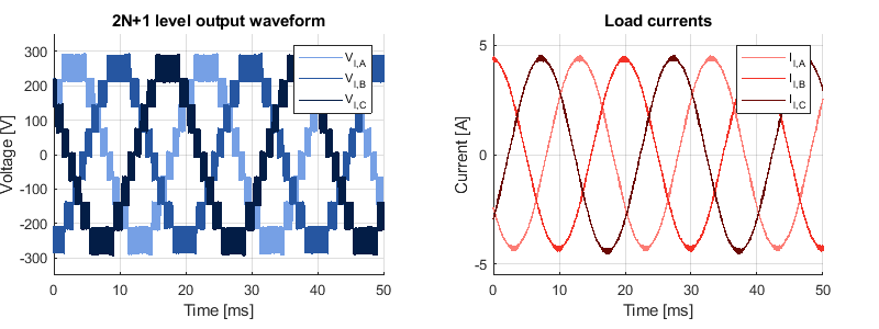
The following plots show the PWM output waveforms of the MMC inverter. As expected, phase-to-neutral voltages show 2N+1 voltage levels, which results in very low ripple load currents.
References
[1] D.G. Holmes, T. Lipo “Pulse Width Modulation for Power Converters”, Wiley, ISBN 0471208140, 2003.
[2] P. W. Hammond, “Medium voltage PWM drive and method,” U.S. Patent 5625545, March 1994.
[3] M. Hagiwara and H. Akagi, “PWM Control and Experiment of Modular Multilevel Converters,” in Proc. PESC Conference, Rhodes, Greece, 2008 (read here).
[4] R. Marquardt, “Stromrichterschaltungen mit verteilten Energiespeichern,” German Patent DE10103031A1, Jan. 24, 2001.


