Table of Contents
Fictive axis emulation is a vector control technique that is mostly used in single-phase inverter applications, where the second axis β of a rotating reference frame needs to be emulated in order to support all vector computations.
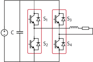
Generally, the control of single-phase systems significantly differs from that of three-phase systems. Notably, numerous well-known concepts such as the separation of direct and quadrature axes – linked to active and reactive power flows – cannot be easily derived from coordinate transformations, simply because only one phase is available! This difference often justifies a preference for specific control techniques such as the use of Proportional Resonant (PR) controllers, rather than conventional vector control in a rotating (also called synchronous) reference frame.
That said, vector control techniques can also be used in single-phase applications, provided that a second axis β is emulated in order to support all vector computations (even though β-related references and quantities may be disregarded at the end of the control process). The benefit of such an approach is that, since coordinate transformations can be used, active and reactive power flows can be manipulated as usual (i.e. within a rotating reference frame).
Software resources
Operating principles of fictive axis emulation
Emulating the beta component
The most obvious technique for emulating the β axis is to delay the available α axis by a quarter period. This results in a simple, yet robust implementation, but which unavoidably impacts the overall control chain due to the said delay. An alternative approach was first proposed by [1], essentially consisting of using an estimator for emulating the current that would flow on the β axis. In practice, this estimator can be easily derived from the plant model, which is needed anyway for the purposes of the control design.
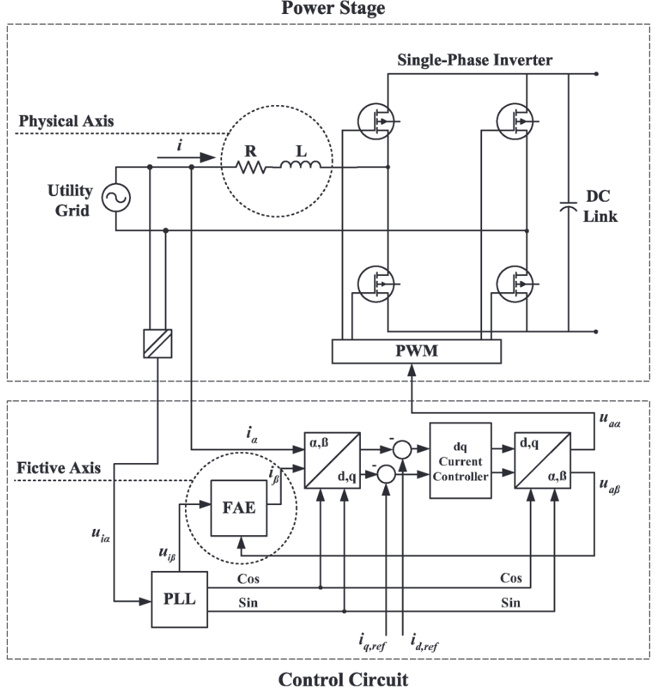
This approach can be easily understood by observing the following figure, taken from [1], which highlights:
- The Physical Axis (α axis), which can be modeled as a first-order system where the current can be physically measured as \(\begin{array}{l}\displaystyle I_\alpha=\frac{1}{sL+R}(V_{g,\alpha}-E_{g,\alpha})\end{array}\).
- The Emulated Axis (β axis), which can re-use the same model for estimating the current that would flow into the system, such as\(\begin{array}{l}\displaystyle I_\beta=\frac{1}{sL+R}(V_{g,\beta}-E_{g,\beta})\end{array}\).
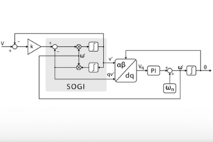
where Vg is the utility grid voltage and Eg is the converter voltage produced between the two phase-legs. In practice, \({l}V_{g,\alpha}\) and \({l}V_{g,\beta}\) are often directly made available by the PLL block, which is implemented using a Second-Order Generalized Integrator (SOGI).
Implementation of fictive axis emulation
FAE for grid-tie inverter in Simulink
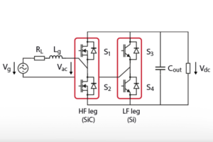
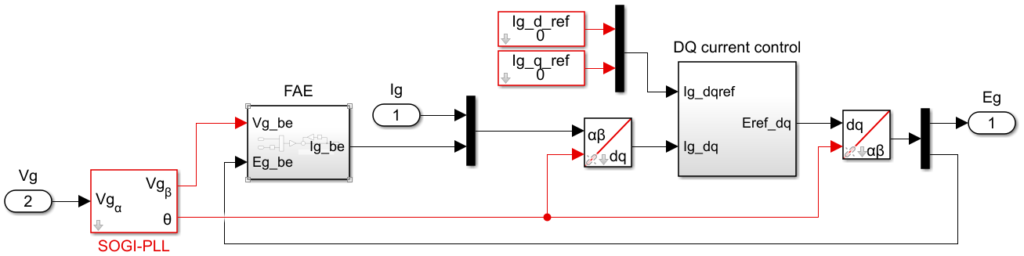
The provided Simulink file implements the inverter grid current control as shown below.
The implementation of the FAE estimator itself is:
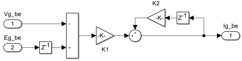
With $$\begin{array}{l}\displaystyle K_1=\frac{T_s}{L_g+R_gT_s}\end{array} and \begin{array}{l}\displaystyle K_2=\frac{L_g}{L_g+R_gT_s}\end{array}$$
FAE in C/C++ code
The imperix IDE provides numerous pre-written and pre-optimized functions. Dedicated routines for fictive axis emulation exist as such within the controllers.h/.cpp files.
As for controllers, FAE-related routines are based on:
- A pseudo-object
FAEparameters, which contains pre-computed parameters as well as state variables. - A configuration function, meant to be called during
UserInit(), namedConfigFAE(). - A run-time function, meant to be called during the user-level ISR, such as
UserInterrupt(), namedRunFAE().
The necessary parameters are documented within the controller.h header file. They are namely:
LandR, the parameter values of the grid inductor (plant).tsample, the sampling (interrupt) period.
The source code of the related routines is given below.
void ConfigFAE(FAEParameters* me, float R, float L, float tsample){
  // Precompute the parameters offline:
  me->a = tsample/(L + R * tsample);
  me->b = L/(L + R * tsample);

  // Initialize the state quantities:
  me->state = 0.0;
}

float RunFAE(FAEParameters *me, float delta){
  // Apply the first-order transfer function:
  me->state = me->a * delta + me->b * me->state;

  return me->state;
}Code language: C++ (cpp)
The code below gives a use case example of both routines:
#include "../API/controllers.h"             // Discrete-time controllers
FAEParameters FAE;                          // Pseudo-object containing the FAE parameters

float R = 0.015;                            // Grid inductor ESR (Ohm)
float L = 0.0025;                           // Grid inductor value (H)

tUserSafe UserInit(void){
  ConfigFAE(&FAE, R, L, SAMPLING_PERIOD);
}

tUserSafe UserInterrupt(void){
  // ... some code
  Ig.imaginary = RunFAE(&FAE, Eg.imaginary - Ug.imaginary);
  // ... some code
}Code language: C++ (cpp)
Academic references
[1] B. Bahrani, A. Rufer, S. Kenzelmann and L. Lopes, “Vector control of single-phase voltage-source
converters based on fictive-axis emulation,” in IEEE Trans. Industry Applications, April 2011.