Table of Contents
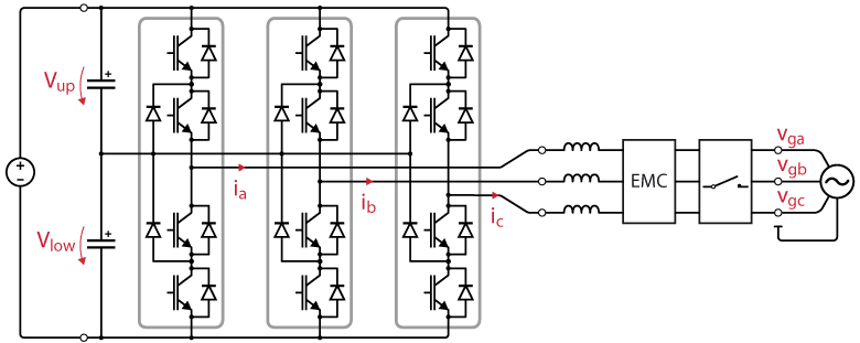
This page provides an example of closed-loop current control for a grid-tied Neutral Point Clamped (NPC) inverter. The considered setup is a three-phase three-wire NPC inverter supplied by a DC source and connected to the grid. An EMC filter is inserted for adequate filtering of the injected currents, and a precharge circuit protects the circuit from uncontrolled in-rush currents.
A first-step introduction to NPC inverters is available in Getting started with an NPC converter, where a simpler open-loop modulation strategy is applied to an NPC inverter connected to a passive load.
Setup description
Involved products
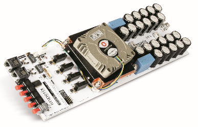
The circuit is shown in Fig. 1. The NPC is built from 3 PEN8018 modules. They are controlled by the B-Box RCP, and the control code is developed with the ACG SDK on Simulink (a valid license is required).
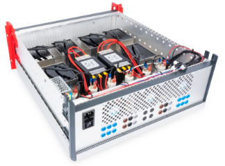
This example uses a passive filter box (for the inductors and the EMC filter), a grid connection panel, and an 800V DC source. The grid voltages are measured with DIN800V voltage sensors.
Assembly and wiring
The wiring of the gating signals and the measurements between the PEN modules and the B-Box controller is identical to that of Getting started with an NPC converter.
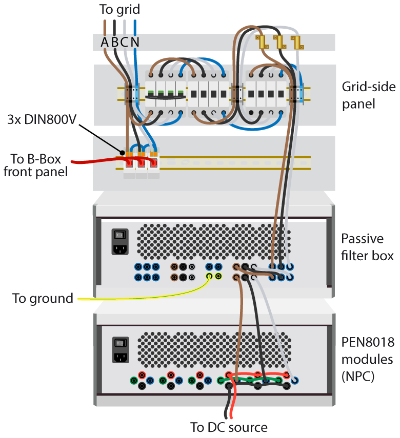
D0H, D1H, D0L and D1L optical outputs of the B-Box RCP, respectively. This is further explained in Getting started with an NPC converter.The wiring of the power stage can be done as proposed in Fig. 2. It is assumed in the following sections that the RJ45 cables going out of the three DIN800V voltage sensors (measure of Vga, Vgb and Vgc, respectively) are connected to the analog inputs 5, 6, 7 of the B-Box front panel.
Configuration of the B-Box front panel
The following table summarizes the parameters to be configured at the B-Box front panel. Similar calculations are described in Getting started with an NPC converter, and more information about the configuration of the B-Box front panel can be found in Analog front-end configuration on B-Box RCP.
| Channels | Measurement | Low Z | Gain | Filter | Limit high | Limit low |
|---|---|---|---|---|---|---|
| 0, 1, 2 | ia, ib, ic | no | 8 | no | 9.4 | -9.4 |
| 5, 6, 7 | vga, vgb, vgc | no | 8 | no | 7.1 | -7.1 |
| 8, 9 | Vup, Vlow | no | 2 | no | 0.5 | -9.0 |
To stop the converter operation in case of abnormal operating conditions, the following protection thresholds are considered for grid current, grid voltage, and DC voltage measurements:
Grid current limits
To limit the grid current to 18A (rating of the PEN module), considering a sensor sensitivity of -46mV/A and an analog gain of 8, the safety limits are set to ±9.4V.
Grid voltage limits
To ensure the grid voltage does not exceed 440V line-to-line (max of filter), considering a sensor sensitivity of 2.46mV/V and an analog gain of 8, the safety limits are set to ±7.1V.
Half-bus DC voltage limits
To ensure neither of the half DC voltages exceeds 450VDC line-to-line (max of PEN module), considering a sensor sensitivity of -9.95 mV/V and an analog gain of 2, the low limit is set to -9V.
Control software
The NPC converter control model developed in Simulink can be downloaded below. Both versions only differ in the modulation technique (carrier-based or space vector modulation).
Carrier-based modulation
Space vector modulation
Current control and grid synchronization
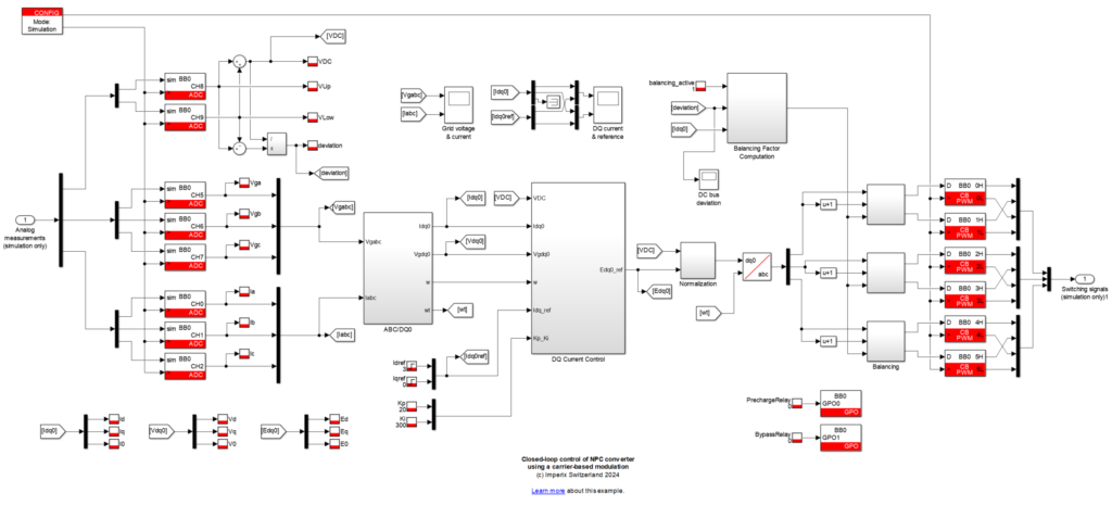
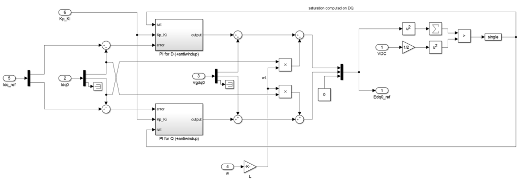
The control of the grid currents is implemented in the grid-synchronous reference frame, as presented in Vector current control. The angle of the reference frame is computed by the DQ-type PLL block from the ACG SDK library. Two PI controllers are used to control the d- and q-axis components of the grid currents separately, followed by feedforward of the grid voltage.
To prevent the integral term of the PI controllers from growing excessively when the actuator is saturated, the controller’s implementation includes an anti-windup (saturation is directly detected in the dq-frame), as shown in Fig. 4. In addition, the integral terms of the PI controllers are kept at reset when the converter is not operating, using the External reset block from the ACG SDK library.
DC bus balancing
Grid-tied operation of NPC converters requires balancing the half DC buses. This note uses an active balancing strategy presented in DC bus balancing of NPC converters. This is required because of the grid non-idealities, – and thus unbalance – that lead to a non-zero average current at the inverter’s midpoint.
Precharge circuit
In this particular use case, precharge through the AC side is not necessary since the DC bus can be precharged from the DC side (DC power source). However, to avoid destructive inrush currents, it is essential that \(V_\text{DC} \ge \widehat{V}_\text{g,LL}\) before connecting the grid.
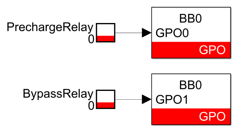
In this example, a grid connection panel is used for protection (circuit breaker) and convenience, as the grid can be connected/disconnected by actuating the relays via the Cockpit interface. To achieve this, the control model contains two tunable parameters PrechargeRelay and BypassRelay, connected to GPO blocks. The physical outputs of the controller GPO0 and GPO1 are wired to the grid connection panel to actuate the precharge and the bypass relays, respectively.
More information about DC bus pre-charging techniques can be found in TN131.
Operating procedure
For safety, the following operating procedure is recommended :
- check that both relays are open ;
- turn on the DC source with respect to \(V_\text{DC} \ge \widehat{V}_\text{g,LL}\) ;
- connect the grid to the grid-side panel ;
- as a precaution, close the precharge relay, and the bypass shortly after ;
- check that the current reference is appropriate (and positive if the DC is not bidirectional) ;
- activate the PWM output signals.
Experimental results
Experimental results measured at nominal operation are shown in Fig. 6, where the current reference for the d-axis is set to 6A at t=0, 15A at t=50ms and 10A at t=100ms.
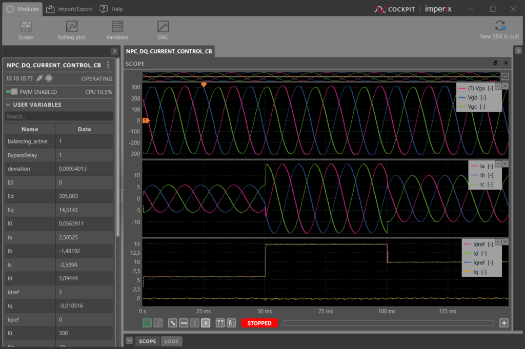
As expected, the reference is well followed, resulting here in an injected current in phase with the grid voltage, since the q-axis current reference is set to zero.


