Table of Contents
This technical note addresses the sensorless control of motor drives using a back-EMF sliding-mode observer. The technique allows speed and position estimation of a Permanent Magnet Synchronous Motor (PMSM) with surface-mounted magnets, without relying on a position or speed sensor.
First, the note introduces the different categories of sensorless motor control methods. Then, the general principles of a Sliding-Mode Observer (SMO) are introduced.
A possible implementation of a back-EMF sliding-mode observer is presented and validated in simulation. It is intended to be used with the ACG SDK on Simulink.
Finally, some experimental results are presented to assess the practical performance of the complete sensorless motor control algorithm. Please note that imperix offers a ready-to-use motor drive system to develop and test motor control techniques. More details can be found in the Motor Testbench quick start guide.
Software resources
Context
Sensorless motor control of a PMSM
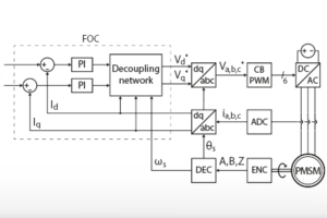
Common control techniques for a Permanent Magnets Synchronous Machine (PMSM) such as Direct Torque Control (DTC) or Field-Oriented Control (FOC) require the knowledge of the rotor position and/or speed.
By definition, the position and the speed of the rotor are linked by the relation:
$$(1) \qquad \omega = \frac{d \theta}{dt}$$
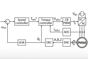
At least one of these two quantities must be known. The speed and/or position of a rotational machine can be measured with an encoder, a resolver, or a tacho-generator. However, these devices increase the cost, the risk of failure, and the mechanical complexity of the drive system.
In order to avoid the drawbacks of the aforementioned measurement devices, the position and speed of the rotor can be estimated from electrical measurements only. In this case, the control algorithm is said to be sensorless. To be clear, sensorless only implies that there is no speed/position sensor, but there is still a need for electrical measurements on the stator to estimate the speed/position of the rotor.
There are two main families of sensorless motor control methods: high-frequency component injection and SMO-based techniques. Thus, the two following sections briefly present these families and justify why this technical note focuses on a Sliding-Mode Observer (SMO).
High-frequency component injection
The first way to estimate the speed and position is to use a high-frequency component injection method, as described in [1]. Essentially, the drive injects a high-frequency voltage component into the stator of the machine. If the frequency is high enough (several hundreds of Hz), the associated torque is null on average because the inertia of the machine prevents it from moving. As the maxima of the associated current vector are related to the alignment of the voltage vector with respect to the axes, the position of the rotor can be inferred from the high-frequency current amplitude. An example of implementation is presented in [1]. This kind of sensorless motor control technique is mainly aimed at PMSMs with interior magnets (IPMSM) because their anisotropy simplifies the detection of the current maxima.
Let us consider the case of a PMSM with surface-mounted magnets (SPMSM). In theory, the machine is isotropic and it is impossible to differentiate the d and q axes by looking at the current maxima. However, in reality, a PMSM is never truly isotropic. At the junction between two magnets, the magnetic flux tends to pass directly from one magnet to the other, rather than passing through the stator windings [2]. Therefore, the flux near the junction does not contribute to the torque generation. As a result, the rotor is always anisotropic, even if the magnets are surface mounted.
Theoretically, this would allow using the high-frequency component injection method with an SPMSM. However, it is not trivial in practice to exploit this small anisotropy. Since this technical note focuses on SPMSM, high-frequency component injection methods are not well-suited.
Back-EMF sliding-mode observer sensorless techniques
The second family of sensorless motor control methods relies on a back-EMF Sliding-Mode Observer (SMO). These techniques stem from the following observation: in a synchronous machine, the frequency of the back-EMF (counter electromotive force) is directly linked to the rotor mechanical speed. Therefore, if one can determine the frequency of the back-EMF – say with a PLL – the angular speed of the rotor is then:
$$(2) \qquad \omega _m = \frac{\omega _s}{p} = \frac{ 2 \pi f_s}{p}$$
where \(p\) is the number of pole pairs, and where \(\omega_m\) and \(\omega_s\) are, respectively, the mechanical and electrical angular speed. Unfortunately, the back-EMF is not observable and must therefore be estimated. A common way to achieve this is to use a Sliding-Mode Observer (SMO) due to its simplicity of implementation and its robustness to parameter variations. Some applications of the sliding-mode observer for sensorless motor control are presented in [3].
Unlike the high-frequency injection methods, back-EMF sliding-mode observers exist in several variants that are suitable for both SPMSMs [4] and IPMSMs [5]. Therefore, it makes sense to consider an SMO in this technical note rather than high-frequency injection methods.
The aforementioned SMO-based techniques suffer from a major drawback: the amplitude of the back-EMF is proportional to the speed of the rotor which means that at low speed, it is difficult to estimate the back-EMF accurately. In particular, at standstill, there is no back-EMF at all, which makes it challenging to start the PMSM in the first place.
Since SMO-based sensorless techniques are not suitable for low-speed control, there is a need to accelerate the PMSM until it reaches a rotational speed “high enough” to get an accurate speed estimation. What is deemed “accurate enough” depends on the application, therefore there is no strict criterion for the minimum operating speed.
General principles of the back-EMF sliding-mode observer
Sliding-Mode Observer
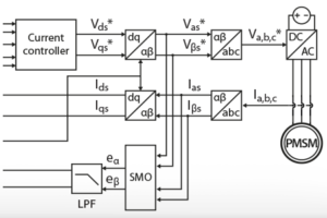
The purpose of the sliding-mode observer is to estimate the back-EMF. At this end, the first step is to identify the back-EMF in the model of a PMSM. Let us consider the voltage balance equations at the stator and the expressions of the stator flux in the synchronous reference frame (SRF) [4]:
$$(3) \qquad \left\{ \begin{array}{ll} \begin{align*}\displaystyle U_{\alpha s} &= R_s I_{\alpha s} + \frac{d \Psi _{\alpha s}}{dt} \\ \displaystyle U_{\beta s} &= R_s I_{\beta s} + \frac{d \Psi _{\beta s}}{dt} \\ \displaystyle \Psi _{\alpha s} &= L_s I_{\alpha s} + \Psi _{PM} \cos \theta _e \\ \displaystyle \Psi _{\beta s} &= L_s I_{\beta s} + \Psi _{PM} \sin \theta _e \end{align*}\end{array}\right.$$
\(U_{\alpha \beta s}\), \(I_{\alpha \beta s}\) and \(\Psi_{\alpha \beta s}\) are the stator phase voltages, phase currents, and flux. \(R_s\) and \(L_s\) are the stator phase resistance and inductance. The rotor flux \(\Psi _{PM}\) is constant and set by the permanent magnets. The equations are expressed in the stationary reference frame and \(\theta _e\) is the position of the rotor in electrical radians.
After a few manipulations, (3) can be re-written as:
$$(4) \qquad \left\{ \begin{array}{ll}\begin{align*}\cfrac{d I_{\alpha s}}{dt} &= -\cfrac{R_s}{L_s } I_{\alpha s} + \cfrac{1}{L_s } U_{\alpha s} – \cfrac{1}{L_s } e_{\alpha} \\ \cfrac{d I_{\beta s}}{dt} &= -\cfrac{R_s}{L_s } I_{\beta s} + \cfrac{1}{L_s } U_{\beta s} – \cfrac{1}{L_s } e_{\beta} \\ \displaystyle e_{\alpha} &= – \Psi _{PM} \,\omega _e \sin \theta _e \\ \displaystyle e_{\beta} &= \Psi _{PM} \,\omega _e \cos \theta _e \end{align*}\end{array}\right.$$
where \(e _{\alpha\beta}\) is the back-EMF. The rotor angle can be directly derived:
$$(5)\qquad \theta _e = – \arctan\left(\cfrac{e_{\alpha}}{e_{\beta}}\right)$$
In(4), the unknowns is \(\theta _e\) and its derivative \(\omega_e\) can be computed with (1). \(U_{\alpha \beta s}\) and \(I_{\alpha \beta s}\) are measurable but the back-EMF must be estimated in order to solve (4).
Here is a common way to estimate the back-EMF with a sliding-mode observer [4]:
- Compute an estimation of the current \(\hat I_{\alpha \beta s} = f(U_{\alpha \beta s}, \hat e_{\alpha \beta})\) from (4)
- Compute the estimation error \(\hat I_{\alpha \beta s} – I_{\alpha \beta s}\)
- Use the error as the input of a switching function [3] and multiply it by a finite gain to ensure the stability of the observer. The system is stable if the gain of the switching function meets the condition \(K_s > \max(|e_{\alpha}|, |e_{\beta}|)\) [4].
Thanks to the feedback of the estimation error, the output of the switching function is a PWM-like signal \(\hat e _{\alpha\beta}\) that approximates the value of the back-EMF. The SMO is robust against parameter mismatch since the feedback will automatically adjust the output of the switching function in order to obtain the value of \(\hat e _{\alpha\beta}\) that corresponds to the actual measured current.
The state variable \(\hat I_{\alpha \beta s}\) is forced to “slide” towards the desired value \(I_{\alpha \beta s}\) by the control action of the switching function, thus the “sliding-mode control”.
Switching function and chattering effect
A basic switching function for the SMO is \(f(x) = \mathop{\mathrm{sgn}}(x)\) [4]. The output signal \(\hat e _{\alpha\beta}\) obtained with the sign function is highly discontinuous. Common control techniques such as DTC and FOC are based on continuous functions, which means that they cannot handle effectively the high frequency components of a discontinuous signal. Their control bandwidth is too narrow for that [3]. The excitation by the high-frequency components leads to oscillations in the control: this phenomenon is called the chattering effect [3].
A first way to mitigate the chattering phenomenon is to use a low-pass filter (LPF) [4]. A first-order LPF introduces a delay (i.e. an error on the estimated angle) that must be compensated [6]. If \(\omega_c\) is the cut-off frequency of the filter, the compensation term is:
$$(6) \qquad \left\{ \begin{array}{ll} \begin{align*} \displaystyle \Delta \hat \theta _e &= \arctan\left(\frac{\hat \omega _e}{\omega _c}\right) \\ \displaystyle \hat \theta &= \hat \theta _e + \Delta \hat \theta _e \end{align*} \end{array}\right.$$
A second way to mitigate the chattering effect is to use a continuous switching function. The so-called sigmoid function is a continuous approximation of the sign function and can be used in SMO algorithms [4].
$$(7) \qquad f(x) = \frac{2}{1 + e^{-a x}} – 1$$
The parameter \(a>0\) defines the smoothness of the transition between -1 and +1. Since the gain of the sigmoid function is smaller than 1 in the transition region, the stability condition of the SMO becomes \(K_s \gg \max(|e_{\alpha}|, |e_{\beta}|)\). The parameters \(a\) and \(K_s\) can be adjusted manually by comparing the real and estimated back-EMF in simulation, for instance.
Speed and position estimation
The position of the rotor can be computed directly from the back-EMF, according to equation (5). From (1), the speed is then obtained by taking the derivative of the rotor angle. Since the output of the arctan function is a sawtooth signal, the estimation of its derivative around the discontinuities needs special care, as explained in PN104.
The arctan method is sensitive to noise because it computes the position directly from the estimated back-EMF. A better alternative is to use a PLL since it has a low-pass characteristic by construction. Since the estimated back-EMF from the SMO has αβ components in quadrature, a Q-PLL is particularly suitable.
In a PLL, the position of the rotor is obtained by integration of the speed, according to (1). However, the angle estimated by the Q-PLL is phase-shifted by \(\pi/2\) to the actual rotor position. The phase shift must be compensated.
$$(8) \qquad \left\{ \begin{array}{ll} \begin{align*} \displaystyle \Delta \hat \theta _e &=\, – \frac{\pi}{2} \\ \displaystyle \hat \theta &= \hat \theta _e + \Delta \hat \theta _e \end{align*} \end{array}\right.$$
Effects of the position estimation error
The electrical angle is used by vector control methods to determine the position of space vectors in the synchronous reference frame (SRF) or to align the rotating reference frame (RRF) with the rotor flux. Therefore, an estimation error on the position will have an effect on the performance of the vector control.
In the case of a Field-oriented control (FOC), the stator current space vector is usually kept aligned on the q-axis to maximize torque production. However, if the estimated position of the RRF is wrong, the current will have a non-zero d-axis component and a smaller q-axis component. The q-axis error will be compensated by the speed controller, while the d-axis error will decrease the torque production per ampere and have an effect on the drive efficiency.
In the case of a Direct Torque Control (DTC), the rotor position is only used to determine in which sector the stator flux is located. The DTC selects the switching vector to apply from a lookup table, depending on the sector. If the rotor position is affected by an estimation error, the DTC may detect the wrong sector and thus, apply a sub-optimal switching vector.
In the case of sensorless control, the error on the position estimation may come from the SMO, the optional LPF, or the PLL. The delay due to the LPF or the integrator can be computed and compensated as in equations (6) and (8).
B-Box Implementation
ACG SDK for Simulink
The technical note I-f startup for sensorless PMSM control (TN137) presents a complete sensorless motor control implementation based on Field-Oriented Control and with a sliding-mode observer. More experimental results are available in this note.
Plant model
In the Simulink implementation, the PMSM was modeled using the PLECS Blockset. The PMSM is driven by an ideal speed source in order to avoid the problem of startup and low-speed operations. The machine is connected to a balanced resistive load and operates in generator mode.
Overview
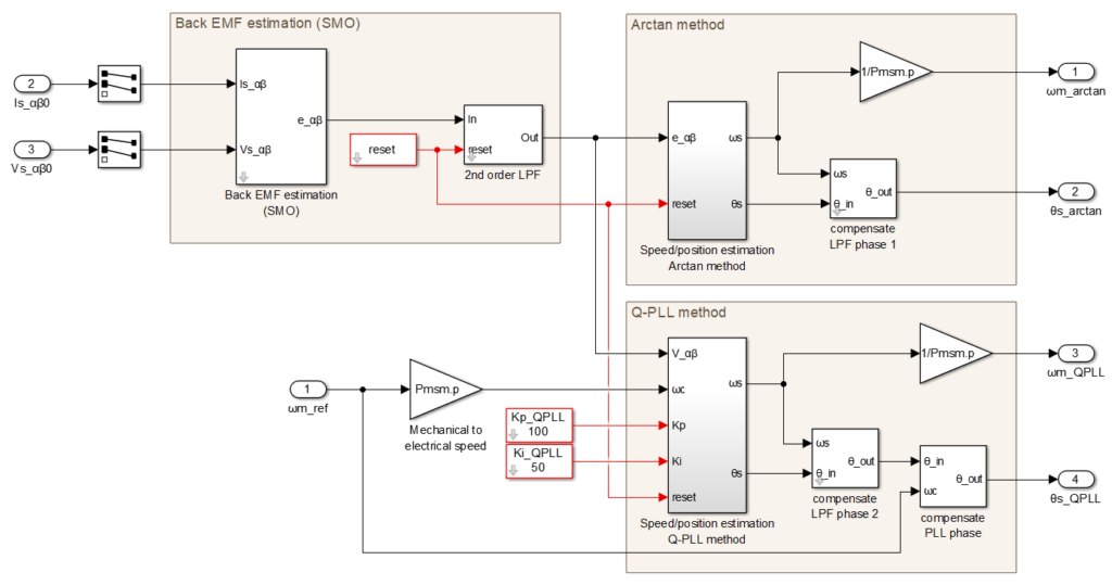
The figure below shows an overview of the sensorless speed/position estimation. The estimated back-EMF is filtered with a 2nd order low-pass filter. The cut-off frequency was chosen empirically to 60 Hz. The speed and position are estimated with both the arctan method and a Q-PLL for comparison purposes.
The gains of the PI controller inside the Q-PLL were determined empirically. Since the PI is of the first order, it has a permanent tracking error when the speed of the machine is not constant. The tracking error can be reduced by using the speed reference as the centering frequency of the PLL.
Sliding-mode observer
The back-EMF is estimated with a sliding-mode observer. The switching function is a sigmoid in order to reduce the chattering effect.

In a practical application, the machine would most likely be driven by an inverter. In this case, the stator voltage is not measurable because it is a switched signal. Instead, the SMO would use the voltage reference of the inverter.
Arctan method
With this first method, the rotor angle is directly computed from the estimated back-EMF with the arctan function. Then, the speed is obtained by taking the derivative of the position, according to (1). With this approach, however, the accuracy of the discrete derivative depends strongly on the discretization period: the longer the period, the more inaccurate it becomes. This undesired effect can be mitigated by filtering the result of the derivative. For the proposed implementation, a low-pass filter with a 1kHz cut-off frequency was added.
Q-PLL
With this second method, the rotor angle is computed with a Q-PLL. Notice that the PLL uses floating-point variables with double precision, whereas the rest of the control is in single precision. The goal is to avoid truncated results due to the limited precision of single-precision variables.

Simulation results
Machine parameters
The position and speed estimations for sensorless motor control were validated in simulation using the following PMSM parameters.
| Model: Control techniques 095U2B300BACAA100190 | ||
| Parameter | Value | Unit |
| Rated power | 1.23 | kW |
| Pole pairs | 3 | – |
| Rated phase voltage | 460 | V |
| Rated phase current | 2.7 | A |
| Rated mechanical speed | 314 | rad/s |
| Rated torque | 3.9 | Nm |
| Stator resistance | 3.4 | Ohm |
| Stator inductance (d and q axis) | 12.15 | mH |
| Flux from permanent magnets | 0.25 | Wb |
| Moment of inertia (PMSM only) | 2.9 | kg cm2 |
Test conditions
- Load torque: PMSM with 200 Ω resistive load on each phase
- Interrupt and sampling frequency: 20 kHz (unless otherwise specified)
- Speed reference: 3000 rpm
Sensorless motor control results
During the simulation, the speed of the PMSM is set to 3000 rpm by an ideal speed source. In addition, the resistive load is perfectly balanced. As a result, the stator current and voltage measurements required by the SMO are perfect sine waves. Under these ideal circumstances, the estimated back-EMF practically fits the true back-EMF, as shown below. The estimated back-EMF is inevitably lagging behind the true value by design: the sliding-mode observer must first observe an error on the current estimation and then adjust the output of its switching function. In the experimental validation presented in TN137, the feedback is delayed by one control period.
In reality, the back-EMF estimation by the SMO is also affected by the noise on the current measurements. As a result, it is still necessary to filter the back-EMF estimation, even if the chattering effect is already attenuated by the sigmoid function. The 2nd order LPF used by the control attenuates the amplitude of the estimated back-EMF. However, it does not affect the speed estimation by the Q-PLL since only the frequency of the signal is relevant.
The difference between the measured and estimated speed/position is negligible, as shown below. This is true for both the arctan and Q-PLL methods.

Experimental results
The simulation is not very realistic because in practice the speed control is not perfect and the measurements are affected by noise. The following figure shows the speed estimations obtained experimentally with the complete sensorless field-oriented control implementation from TN137. The peak estimation error at nominal speed is in the order of 6% with the Q-PLL and 8% with the arctan method. Qualitatively speaking, the PLL estimation is also “smoother” than with the arctan method. The difference can be explained by the measurement noise on the current measurements: the PLL has a low-pass filter characteristic that partially attenuates this noise, whereas the arctan method has no filtering at all. Therefore, even if the arctan method seems to offer similar performance to the Q-PLL, the Q-PLL is more appropriate in practice due to its better immunity to measurement noise.
Academic references
[1] A. Consoli, G. Scarcella and A. Testa, “Industry application of zero-speed sensorless control techniques for PM synchronous motors,” in IEEE Transactions on Industry Applications, vol. 37, no. 2, pp. 513-521, March-April 2001, doi: 10.1109/28.913716.
[2] D. Hanselman, “Brushless Permanent Magnet Motor Design”, 2nd edition, Magna Physics Publishing, USA, 2006, ISBN: 1-881855-15-5
[3] V. I. Utkin, “Sliding mode control design principles and applications to electric drives,” in IEEE Transactions on Industrial Electronics, vol. 40, no. 1, pp. 23-36, Feb. 1993, doi: 10.1109/41.184818.
[4] Yongchang Zhang and Jiali Liu, “An improved Q-PLL to overcome the speed reversal problems in sensorless PMSM drive,” 2016 IEEE 8th International Power Electronics and Motion Control Conference (IPEMC-ECCE Asia), Hefei, 2016, pp. 1884-1888, doi: 10.1109/IPEMC.2016.7512582.
[5] Wang Gaolin, Zhang Guoqiang and Xu Dianguo, “Rotor position estimation with full-order sliding- mode observer for sensorless IPMSM,” Proceedings of The 7th International Power Electronics and Motion Control Conference, Harbin, 2012, pp. 2577-2581, doi: 10.1109/IPEMC.2012.6259265.
[6] Z. Ma and X. Zhang, “FPGA Implementation of Sensorless Sliding Mode Observer With a Novel Rotation Direction Detection for PMSM Drives,” in IEEE Access, vol. 6, pp. 55528-55536, 2018, doi: 10.1109/ACCESS.2018.2871730.


