Table of Contents
This page presents a first HIL example to get started with a B-Box RCP and an OPAL-RT OP4510. Although validated with an OP4510, the provided files can be adapted to the new OP4512 or other OPAL-RT simulators.
The considered circuit, shown in Fig. 1, implements a dual-stage conversion structure, using a boost DC/DC stage in order to raise the voltage of the PV panel to an intermediate DC bus, as well as a two-level DC/AC inverter for the connection to the grid.

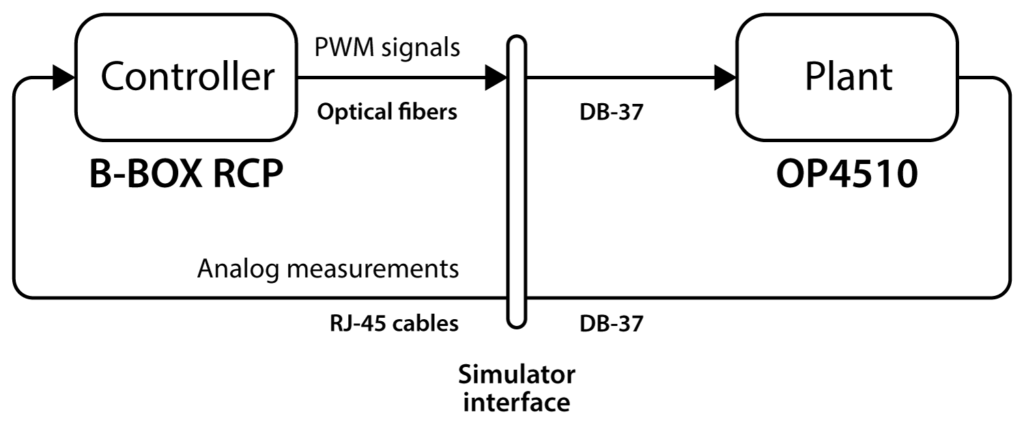
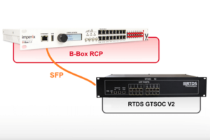
While the real-time control is managed by the B-Box RCP (as for a real power stage), the plant is emulated in the OP4510. This configuration is often referred to as C-HIL (Controller Hardware-In-the-Loop), which is explained in detail in TN178. This scenario is depicted in Fig. 2.
This emulated circuit is a simplified version of the one provided in the AN006, where a more detailed introduction to the circuit and a description of the controller implementation are available.
Considered software setup
This example was created with the following software versions:
- Imperix ACG SDK 2024.1
- Matlab 2022b
- OPAL-RT RT-LAB 2024.1
Downloads
The Simulink model running in the B-Box RCP and the RT-LAB project running in the OP4510 are available below.
Physical setup
Hardware requirements
Imperix and OPAL-RT products :
- 1x Imperix B-Box RCP
- 1x Imperix Simulator Interface for OPAL-RT
- 1x OPAL-RT OP4510
Additional components :
- 9x RJ-45 cables
- 8x optical fibers
Wiring
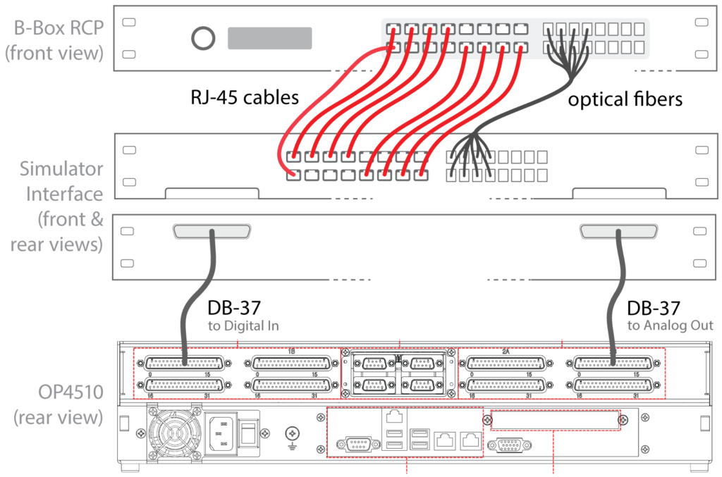
The wiring is depicted in Fig. 3. Power supply and Ethernet connections of both the B-Box RCP and the OP4510 are not shown.
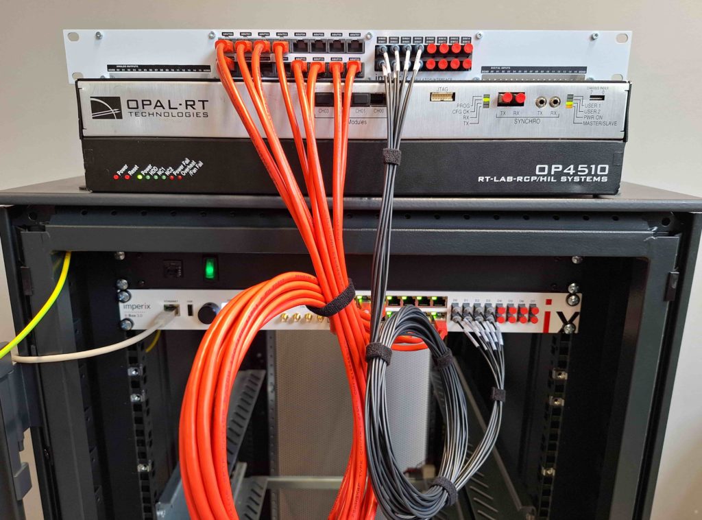
The final setup is shown in Fig. 4.
Step-by-step setup guide
Launch the plant simulator (OP4510)
To launch the simulator,
- Open RT-LAB and select/create a workspace.
- Make sure that your simulator is listed in the ‘Targets’ list of the Project Explorer. Then, make sure that the simulator is reachable by double-clicking on it and checking that the ‘State’ field is ‘up’.
- To import the project, click on File > Import > Existing RT-LAB Project, select ‘Select an archive file’ and set the path to this example’s archive. Press ‘Finish’.
- Double-click on the project to open it.
- To open the model’s overview, expand ‘Models’ and double-click on the model in the project hierarchy.
- Build, load and execute the model by clicking on ‘Build’, ‘Load’ and ‘Execute’ in the Operations tab on the right.
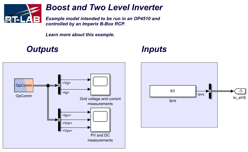
When loading the RT-LAB project on the OP4510, another Simulink model is automatically generated and opened by RT-LAB. This new model can be used to monitor measured quantities through scopes, or set the PV panel output current (see Ipvs on Fig. 5).
Launch the real-time controller (B-Box RCP)
From the B-Box RCP point of view, there is no difference between a HIL simulation – as in this example – and controlling a real power converter: the controller receives analog measurements produced by the simulator and generates in return PWM signals through optical transmitters.
To launch the controller,
- On the B-Box front panel, set the gains of channels 0-3/12-15 to 4 and the gain of channel 8 to 2. More information about the front panel configuration can be found in the PN105.
- Open the Simulink model and check that ‘Automated Code Generation’ is selected in the Configuration block.
- Press Ctrl+B to build the code. Cockpit will automatically launch at the end of the build process.
- In Cockpit, select the B-Box based on its IP address and press ‘OK’ to open the project.
- Add scopes to monitor the signals of interest (e.g. Vg,abc, Ig,abc).
When ready to operate, enable the PWM in the project sidebar on the left.
Results
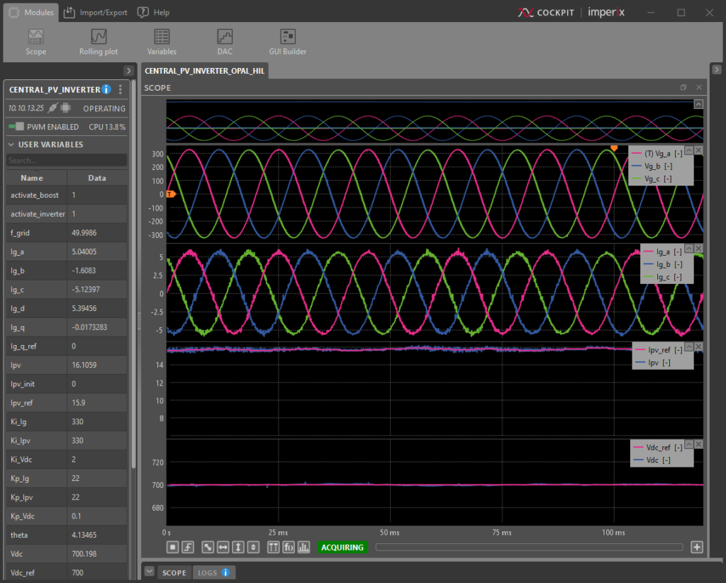
Expected results are shown in Fig. 6. One can easily verify that injected current is in phase with the grid voltage, while the PV current and DC bus voltage follow the desired references.
Additional useful hints
Sensitivity and gain
The Imperix model is ready to operate with a real power stage (e.g. using imperix products): appropriate sensors are already selected in the ADC blocks, explaining why the considered sensitivity can vary among the measured quantities. Those variations are already taken into account in the power circuit from the RT-LAB project, where gains for the analog output have been set adequately.
The programmable gains (x1, x2, x4 or x8) set in the ADC Simulink blocks must match those set on the B-Box front panel.
Interface power supply
As indicated in the datasheet, the Simulator Interface for OPAL-RT is supplied with 12V through the pin #17 of the DB-37 connector. If the interface is not working properly, it is recommended to check that voltage.
In case this voltage is not sufficient (i.e. < 12V), the interface can be supplied with an external DC source via the GND and 12V pins (see Fig. 7).
Use other IO channels
Used channels can be easily changed. For instance, if channel 9 must be used instead 8 for the Vdc measurement, the following changes can be followed:
- Change the Input channel number accordingly in the Imperix ADC block in the B-Box Simulink model.
- Physically, move the RJ-45 cable from RJ-45 port 8 to 9 on the B-Box front panel and on the interface. Ensure that the programmable gain of channel 9 is correct (2, in this example) on the B-Box front end.
- In the Simulink model of the RT-LAB project, move from the top-level to the ‘SM_eHS’ subsystem and double-click on the ‘eHS’ block. This will open the power circuit model in the OPAL-RT Schematic Editor. From there, select the Vdc voltage sensor and click on ‘AO’ in the right side panel. Then, change the pin parameter from ‘Slot 2B Channel 08′ to Slot 2B Channel 09’.


