Table of Contents
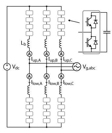
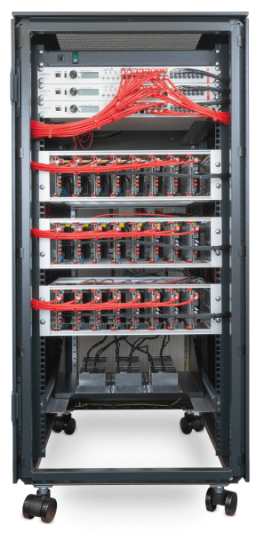
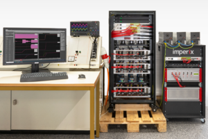
This example shows the essential elements of a control implementation for a grid-tied nine-level MMC converter consisting of 24 submodules (Figure 1). The control is meant to be implemented with three B-Box RCP units, using the automated code generation process (ACG). The employed hardware equipment and system parameters are that of the standard MMC test bench (Figure 2). As such, this example is also meant to serve as a ready-made template for any control developments intended on this hardware.
The selected control approach is inspired from [1], which is one of the simplest possible control approaches including the complete closed-loop control of all state variables. CB-PWM modulators are therefore used. Regarding modulation with integrated balancing, such as using the well-known sort-&-select approach (SS-PWM), readers are invited to consult TN160.
The related Simulink files contain not only the control implementation but also a model of the plant. Hence, these files can be simultaneously used for simulation and automated code generation purposes.
Downloads
The complete simulation and control files are contained in:
All Simulink sheets are commented on so that their operation can be easily understood. The init.m file is automatically called at the beginning of the simulation or code generation process (using the Init callback of the *.slx file).
Minimum requirements:
- Imperix ACG SDK 3.6.0.0 or newer.
- MATLAB Simulink R2017b or newer.
Operation principles of the MMC converter
In this example, the implementation for the MMC converter is designed as a centralized control. Therefore, one single control file – in Simulink – is used for the complete control. At the hardware level, this corresponds to implementing one single controller built using three stacked B-Boxes (one master, two slaves).
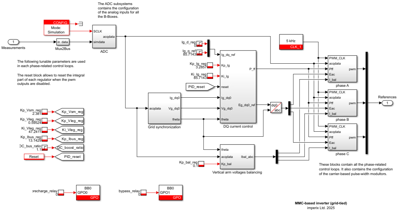
Regarding the control software, the implementation is largely inspired by [1], which is a key reference regarding the control of MMC converters with carrier-based modulation. However, two minor differences are present – and somewhat recommended – between [1] and this example:
- The arm-level vertical energy balancing is not achieved indirectly through the so-called averaging control, but instead is done explicitly by an associated controller, acting on the circulating current of each leg in such a way that the total DC current is unchanged. A recommended reference on this topic is [2].
- The DC-side dynamics are improved by feed-forwarding the AC-side active power into the DC-side current control. Indeed, this facilitates the control of the total embedded energy, i.e. overall average capacitor voltage. More subtle approaches can be used, which are typically relevant in case of operation under unbalanced grid conditions, or single-phase systems.
Hardware and software configuration
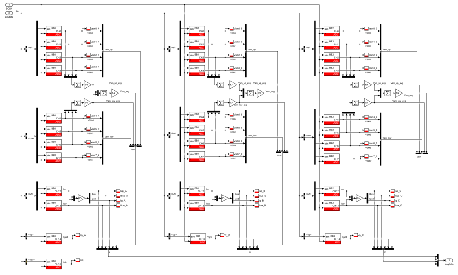
The configuration of all analog inputs for the complete MMC converter is entirely contained within the ADC subsystem (Fig. 4), where all the ADC configuration blocks are conveniently grouped.
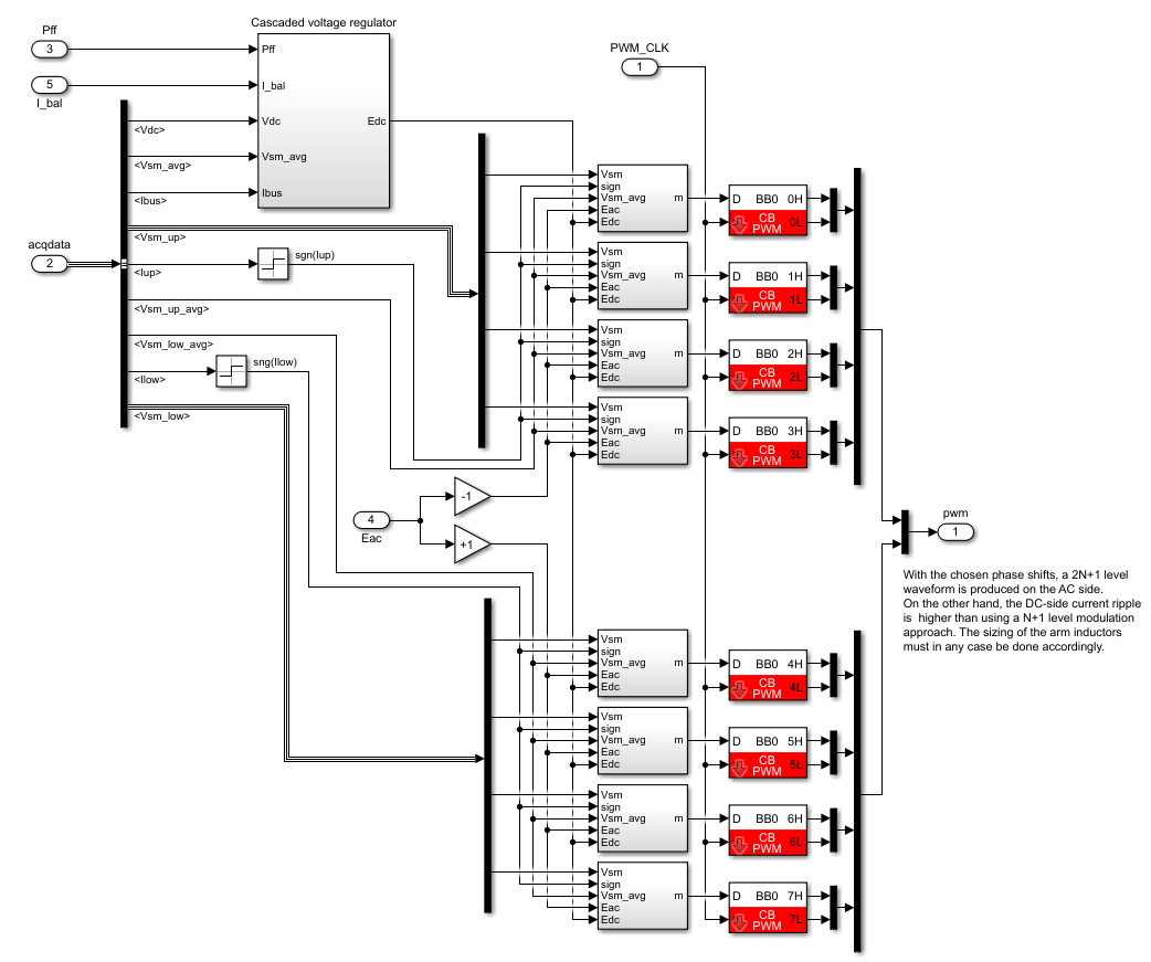
Similarly, for each phase, the associated subsystem (Fig. 5) contains the carrier-based modulators (CB-PWM) linked to each submodule, which are phase-shifted according to the desired modulation pattern. Also, each modulator receives here a duty-cycle that is slightly altered by a local voltage controller, responsible for maintaining the appropriate charge level inside the submodule capacitors(s).
Important comments
- Several controllers are sharing the same parameters (Kp, Ki). Indeed, these parameters are implemented in the top level of the MMC converter control software and they are shared with Goto and From blocks. This translates into so-called Simulink global signals, which are visible throughout a Simulink model. More subtle approaches are possible.
- There is no start-up/shut-down procedure implemented in the Simulink files. When needed, such mechanisms can be implemented, for instance using Stateflow. An example is given in TN131. However, for complex projects, a control implementation using C/C++ may be preferable.
- We recommend using Simulink’s sample time highlighting options to control the exact execution rate of each block. These options are conveniently available from the menu Display >> Sample Time >> Colors. Indeed, inappropriate execution rates are a common source of mismatch between simulation and the actual real-time control implementation. The note PN135 provides more details on this topic.
Illustrative simulation results of the MMC converter
Figure 6 shows some simulation results from the presented example:
Experimental results
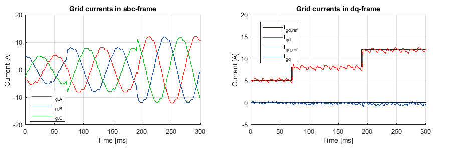
The following figures show typical experimental results when the MMC converter is connected directly to the 230/400V AC grid. Several remarks can be made:
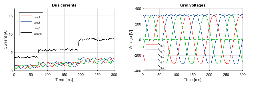
- Current reference steps are properly followed (figure 7, right). The remaining imperfections on the grid currents are related to dead-time distorsion, which is not compensated.
- Another source of distortion is the poor quality of the grid voltage available at imperix’s premises, which is clearly visible (figure 8, right).
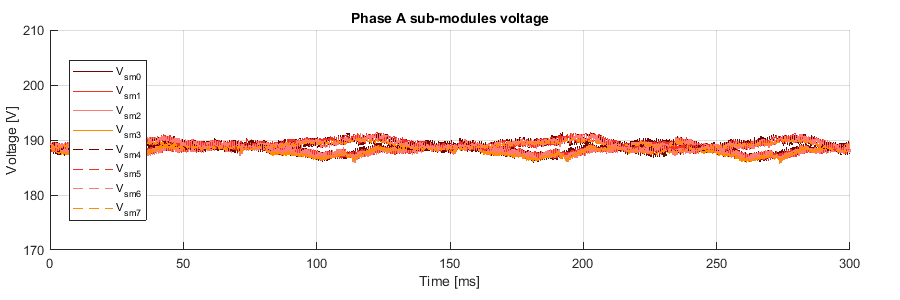
- Thanks to the feed-forwarding of the AC-side total power into the DC-side dynamics, the total DC bus current quickly replicates the AC power changes (figure 8, left). This results in no visible over- or under-shoot in the total converter energy, which is visible from the submodule capacitor voltages (figure 9).
To go further
In [1], other modular multi-level converter topologies are presented, including the star-connected cascaded H-bridge converter. The control of a cascaded H-bridge with interleaved carrier-based PWM is detailed in TN165 and can be applied to modern cascaded converter concepts, such as solid-state transformers(AN015) and transformerless medium-voltage STATCOMs (AN013).
References
[1] M. Hagiwara, H. Akagi, “Control and Experiment of Pulsewidth-Modulated Modular Multilevel Converters,” in IEEE Transactions on Power Electronics, Vol.24, July 2009.
[2] P. Münch, D. Görges, M. Izák and S. Liu, “Integrated current control, energy control and energy balancing of Modular Converters,” in Proc. IECON Conference, Phoenix, 2010.


