Table of Contents
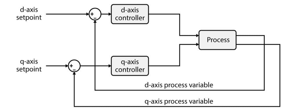
Vector current control (also known as dq current control) is a widespread current control technique for three-phase AC currents, which uses a rotating reference frame, synchronized with the grid voltage (dq-frame).
First, the note introduces the general operating principles of vector current control and then details a possible design methodology.
Then, an example of vector current control for a two-level inverter is provided. A possible control implementation on the B-Box RCP or B-Board PRO is introduced for both C/C++ and Simulink/PLECS implementations. Finally, simulation and experimental results are compared and discussed.
General principles of vector current control
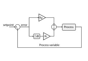
In DC applications, conventional PI controllers provide excellent performance, notably minimal steady-state error, thanks to the (almost) infinite DC gain provided by the integral control action. However, in AC applications, PI controllers inevitably present a delayed tracking response, because their gains cannot be set high enough to avoid a steady-state error.
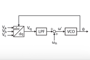
A well-known countermeasure to this shortcoming is the implementation of the PI controller(s) within a rotating reference frame (dq), which allows to “re-locate” the (almost) infinite DC gain at the desired frequency. This technique requires the rotating reference frame to be synchronized with the grid voltage, which is often achieved using a phase-locked loop PLL.
– DQ-type or SRF PLL (TN103): a standard technique for most applications
– SOGI-based PLL (TN104): a more advanced technique for distorted or unbalanced conditions.
In practice, once the reference frame is established, the use of the Clarke and Park transformations allows projecting all stationery quantities (abc) into direct and quadrature quantities (dq). The control of the AC current becomes therefore transformed into a new control scenario, consisting of two DC currents. Both currents can then be controlled using conventional PI controllers, with zero steady-state error.
Inverter current control example
In this note, it is proposed to study the vector current control of a two-level inverter. This example features two state variables: the grid current on the d-axis \(I_{g,d}\) and on the q-axis \(I_{g,q}\).
Using general Kirchhoff circuit laws, the fundamental voltages generated by the inverter are expressed as:
$$ \begin{aligned}[c] E_{a} &= R_g I_{g,a} + L_g \frac{di_{g,a}}{dt} + V_{g,a} \\ E_{b} &= R_g I_{g,b} + L_g \frac{di_{g,b}}{dt} + V_{g,b} \\ E_{c} &= R_g I_{g,c} + L_g \frac{di_{g,c}}{dt} + V_{g,c} \end{aligned}$$
In a dq rotating reference frame synchronized with the grid voltages, this is translated into:
$$ \begin{aligned}[c] E_{d} &= R_g I_{g,d} + L_g \frac{di_{g,d}}{dt} -\omega_g L_g I_{g,q} + V_{g,d} \\ E_{q} &= R_g I_{g,q} + L_g \frac{di_{g,q}}{dt} +\omega_g L_g I_{g,d} + V_{g,q} \end{aligned} $$
In the Laplace domain, the d- and q-axis currents are expressed as:
$$ \begin{aligned}[c] I_{g,d} = \frac{1}{R_g + s L_g} (E_d – V_{g,d} + \omega_g L_g I_{g,q}) \\ I_{g,q} = \frac{1}{R_g + s L_g} (E_q – V_{g,q} – \omega_g L_g I_{g,d}) \\ \end{aligned} $$
Note that the mathematical transformation brings coupled terms, that are proportional to the grid angular frequency \(\omega_g\). These terms will be compensated in the next section to achieve decoupled control of both d- and q-axis currents.
System-level modeling
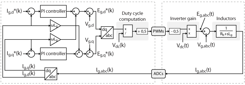
A widely-accepted model for the proposed system is shown below. Four distinct parts can be clearly identified.
Plant
The inductor is modeled as:
$$ P_1(s) = \displaystyle\frac{K_1}{1+s T_1} \qquad \text{with} \qquad \begin{cases}K_1 = 1/R_g \\ T_1 = L_g/R_g \end{cases} $$
Measurements
The measurements of the currents \(I_{g,abc}\) are generally modeled using a low-pass filter approximation, or they are neglected. The sampling corresponds to a zero-order hold (ZOH) that introduces a lag corresponding to the sampling delay.
Control
The control algorithm consists of two digital PI controllers followed by some basic mathematics operations to compute the duty cycles. The whole algorithm requires a certain amount of computation time, which is modeled as a delay.
Modulation
The Pulse-Width Modulation (PWM) is also generally modeled as a simple delay.
Tuning and performance evaluation
Different methods are proposed in the literature to determine the parameters of a PI controller. Those methods are well detailed and explained in [1]. In this note, the Magnitude Optimum (MO) will be used.
The goal of the MO is to make the frequency response from reference to the plant output as close to one as possible for low frequencies. It can be shown that the corresponding optimal controller parameters \(K_p\) and \(K_i\) are:
$$ K_p = \frac{T_1}{2K_1 T_d}=\frac{L_g}{2T_d} \quad \quad \quad K_i = \frac{1}{2K_1 T_d}=\frac{R_g}{2T_d}$$
The parameter \(T_d\) represents the sum of all the small delays in the system, such as the computation delay or the modulation delay mentioned above. The product note Time delay determination for closed-loop control (PN142) explains how to determine the total delay of the system.
Academic references
[1] Karl J. Åström and Tore Hägglund; “Advanced PID Control”; 1995
B-Box / B-Board implementation
Software resources
PLECS model
using PLECS for plant simulation
Minimum requirements:
Imperix ACG SDK ≥3.6.1 | PLECS ≥ 4.5.9
Simulink model
using Simscape for plant simulation
Minimum requirements:
Imperix ACG SDK ≥3.6.1 | MATLAB Simulink ≥R2016a | [offline simulation only] Simscape (paid license)
C/C++ code
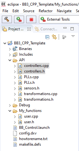
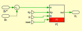
The imperix IDE provides numerous pre-written and pre-optimized functions. Controllers such as P, PI, PID and PR are already available and can be found in the controllers.h/.cpp files.
As for all controllers, PI controllers are based on:
- A pseudo-object
PIDcontroller, which contains pre-computed parameters as well as state variables. - A configuration function, meant to be called during
UserInit(), namedConfigPIDController(). - A run-time function, meant to be called during the user-level ISR, such as
UserInterrupt(), namedRunPIController().
Implementation example
#include "../API/controllers.h"
PIDController mycontroller_d;
PIDController mycontroller_q;

float Kp = 10.0;
float Ki = 500.0;
float limup = 500;
float limlow = -500;

tUserSafe UserInit(void)
{
    ConfigPIDController(&mycontroller_d, Kp, Ki, 0, limup, limlow, SAMPLING_PERIOD, 0);
    ConfigPIDController(&mycontroller_q, Kp, Ki, 0, limup, limlow, SAMPLING_PERIOD, 0);
    return SAFE;
}
tUserSafe UserInterrupt(void)
{
    //... some code
    Egd_ref = RunPIController(&mycontroller_d, Igd_ref - Igd) + Vgd - w*L*Igq;
    Egq_ref = RunPIController(&mycontroller_q, Igq_ref - Igq) + Vgq + w*L*Igd;
    //... some code
    return SAFE;
}Code language: C++ (cpp)
Simulink implementation of vector current control
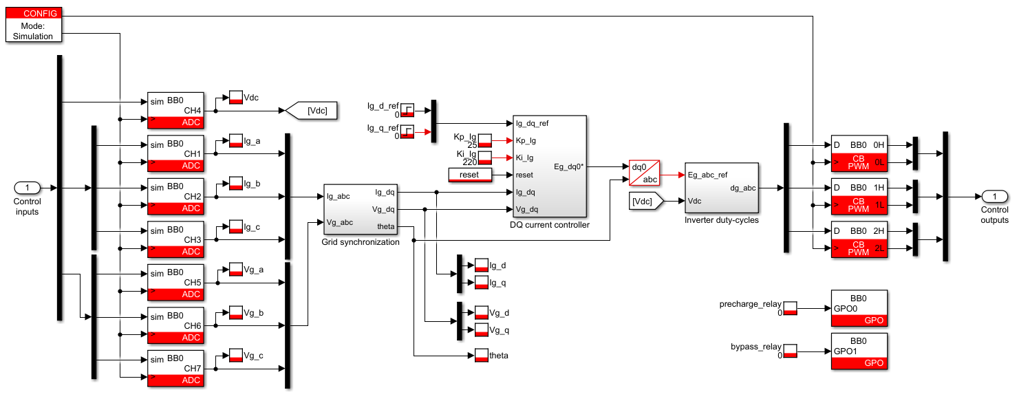
The attached file provides a typical current control implementation for a grid-connected inverter. Alternatively, a simplified version of this control can be found in the space vector modulation (SVM) note with a passive RL load.
PLECS implementation of vector current control
The included file for PLECS also provides a PI controller block. The default PI block of the PLECS library can be used as well.
Results of vector current control
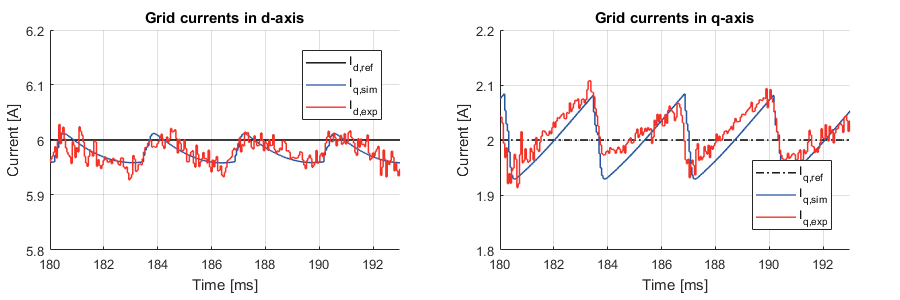
The vector current control was tested with a grid-connected inverter. A current reference step on both the d-axis and the q-axis was performed in simulation and experimental modes. The following graphs show a comparison between both results:
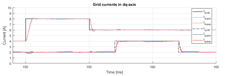
Small differences can be observed between the simulation and the experimental results, which can be explained by the following facts:
- In simulation, the variable transformer is not taken into account (modeled). The transformer increases the total inductance between the converter and the grid, which in turn increases the inertia of the system.
- The EMC filter used to reduce the common-mode current is also not modeled in the simulation.
A ripple can be observed on the real grid currents in dq-frame. The frequency of the ripple is 300Hz, or 6 times the output fundamental frequency. This phenomenon can be reproduced in simulation by properly taking into account the effect of the dead-time between the complementary PWM signals. In the imperix CB-PWM block, this can be achieved by simply activating the simulation of dead-times. The simulation of dead-times allows a slightly better accuracy but significantly slows down the simulation. The following picture shows a comparison between the new simulation and the experimental results.
